Honeywell HP400ULM Installation Instructions - Page 4
Battery Stand-By Mode Specification Chart, Output Battery, Capacity, STBY/ALRM, 4Hr Stand-By
 |
View all Honeywell HP400ULM manuals
Add to My Manuals
Save this manual to your list of manuals |
Page 4 highlights
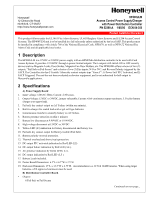
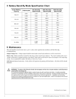
5 Battery Stand-By Mode Specification Chart Output Battery Capacity 12Ah-12V 17Ah-12V 55Ah-12V 12Ah-24V 17Ah-24V 55Ah-24V STBY/ALRM STBY ALRM STBY ALRM STBY ALRM STBY ALRM STBY ALRM STBY ALRM 4Hr Stand-By 15Mins/ALRM 2.00A 3.50A 2.00A 3.50A 3.50A 3.50A 2.00A 3.50A 2.00A 3.50A 3.50A 3.50A UL Listing UL294 UL603 24Hr Stand-By 15Mins/ALRM N/A N/A 200mA 2.00A 1.50A 3.50A N/A N/A 200mA 3.50A 1.50A 3.50A UL294 UL603 UL1481 60Hr Stand-By 5Mins/ALRM N/A N/A N/A N/A 300mA 3.50A N/A N/A N/A N/A 300mA 3.50A UL1481 6 Maintenance This unit should be tested at least once a year to verify correct operation in accordance with the following recommendations; Output Voltage Test - Voltage output should be tested under normal load conditions to verify correct levels. Battery Test - Battery should be checked for full charge under normal load conditions. This check should verify correct voltage at both battery terminals and also at the Battery output point on the board to ensure the integrity of all connecting wiring. It is recommended to replace the battery at least every 4 years. LED Test (distribution board only) - Verify yellow LED operation by pushing LED test button. All yellow LED's should illuminate. ! WARNING: To reduce risk of electric shock, do not expose unit to rain or excess moisture, and disconnect power before servicing unit. For continuous protection against hazard, replace fuses only with exact type and rating. A readily accessible switched circuit breaker must be available to disconnect main power as required. All power limited wiring should be routed so that it cannot touch non-power limited wiring; minimum spacing 1/4". Installation and servicing should only be made by qualified personnel; contains no user-serviceable parts. Install in accordance with all local regulations and the National Electrical Code. Continued on next page... 4 HP400ULM Installation Document P/N 52390:A 1/05/06
-
 1
1 -
 2
2 -
 3
3 -
 4
4 -
 5
5 -
 6
6
 |
 |
