Honeywell IS215T Installation Instructions - Page 1
Honeywell IS215T Manual
 |
View all Honeywell IS215T manuals
Add to My Manuals
Save this manual to your list of manuals |
Page 1 highlights
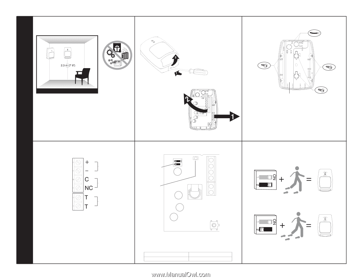
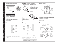
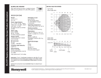
IS-215T Passive Infrared Motion Sensor Installation Instructions ❶ Select the mounting location. ❷ Separate the sensor housings and remove the printed circuit board (PCB). • Use a small screwdriver to push in the housing latch at the bottom of the sensor, and gently pull apart the housings. ❸ Mount the unit. Wiring Knockouts Corner Mount Corner Mount Mounting Location Guidelines • 2.3 m (7'6") mounting height • Avoid direct or reflected sunlight • Aim sensor away from windows or heating/ cooling devices • Sensor must have a clear line-of-sight to protected area ❹ Wire the unit. POWER 12VDC 10mA ALARM 16VDC 90mA TAMPER 30VDC 0.5A • Push outward on the PCB latch and lift the PCB out of the housing. ❺ Configure the sensor sensitivity. Switch Alarm LED Wall Mount Wire Channel • Slide the wire through the wire channel and wire access in the back housing. • Mount the back housing flat against a wall or in a corner. • Replace the PCB. ❻ Walk-test the sensor. High Sensitivity: 2-4 Steps (Pulse Count 1) Low [Normal] Sensitivity: 3-5 Steps (Pulse Count 2) • Connect wires as shown using 0.64 - 1.63 mm2 (14 to 22 AWG) wire size. Observe proper polarity. • Configure the IS-215T for the sensitivity best suited to the application. SENSITIVITY SWITCH SW2 POSITION High (pulse count 1) ON Low [Normal] (pulse count 2) OFF
-
 1
1 -
 2
2
 |
 |