Honeywell MS1690 User Guide - Page 8
Scanner Components, Item Description
 |
View all Honeywell MS1690 manuals
Add to My Manuals
Save this manual to your list of manuals |
Page 8 highlights
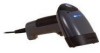
INTRODUCTION Scanner Components Figure 1. Scanner Components Item Description 1 Yellow LED See Visual Indicators (on page 17) 2 White LED 3 Blue LED See Visual Indicators (on page 17) See Visual Indicators (on page 17) 4 Speaker See Audible Indicators (on page 16) 5 Trigger 6 Red Window 7 Cable Release LED Aperture See The PowerLink Cable (on page 5) 8 Cable Connection 10-pin RJ45, Female Socket, See Scanner Pinout Connections (on page 34) 4
-
 1
1 -
2
-
 3
3 -
 4
4 -
 5
5 -
 6
6 -
 7
7 -
 8
8 -
 9
9 -
 10
10 -
 11
11 -
 12
12 -
 13
13 -
14
-
15
-
16
-
17
-
18
-
19
-
20
-
21
-
22
-
23
-
24
-
25
-
26
-
27
-
28
-
29
-
30
-
31
-
32
-
33
-
34
-
35
-
36
-
37
-
38
-
39
-
40
-
41
-
42
-
43
-
44
-
45
-
46
-
47
-
48
-
49
-
50
-
51
-
52
 |
 |

4
I
NTRODUCTION
Scanner Components
Figure 1. Scanner Components
Item Description
1
Yellow LED
See
Visual Indicators
(on page 17)
2
White LED
See
Visual Indicators
(on page 17)
3
Blue LED
See
Visual Indicators
(on page 17)
4
Speaker
See
Audible Indicators
(on page 16)
5
Trigger
6
Red Window
LED Aperture
7
Cable Release
See
The PowerLink Cable
(on page 5)
8
Cable Connection
10-pin RJ45, Female Socket,
See
Scanner Pinout Connections
(on page 34)