Honeywell RTH1120 Owner's Manual
Honeywell RTH1120 Manual
 |
View all Honeywell RTH1120 manuals
Add to My Manuals
Save this manual to your list of manuals |
Honeywell RTH1120 manual content summary:
- Honeywell RTH1120 | Owner's Manual - Page 1
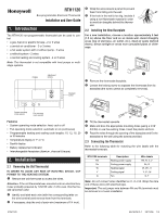
Thermostat Installation and User Guide 1. Introduction The RTH1120 non-programmable thermostat can be used to control: • a gas, fuel oil or electric furnace - 2 or 3 wires • a central air conditioner - 2 or 3 wires • a hot water system with or without pump - 2 wires • a millivolt system - 2 wires - Honeywell RTH1120 | Owner's Manual - Page 2
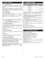
batteries are installed, mount the thermostat on the baseplate. o Secure the thermostat using the locking screw and install the faceplate. p Apply power back to the system. Fan relay Heat relay Cool relay Note: Remove the red jumper wire between terminals Rc and Rh. RTH1120 69-1875EF-1 29/11 - Honeywell RTH1120 | Owner's Manual - Page 3
mode (ON). Note: This switch is not used if you have a 2-wire installation as the fan is not connected to the thermostat. AUTO The fan operates only when the heating or cooling system is On ( volatile Dimensions: 5 in. x 3 in. x 1 in. (127 mm x 75 mm x 28 mm) RTH1120 69-1875EF-1 29/11/06 3/4 - Honeywell RTH1120 | Owner's Manual - Page 4
ON15-02H, Honeywell Limited/Honeywell Limitée, 35 Dynamic Drive, Scarborough, Ontario M1V4Z9. 7. Customer Assistance If you have any questions about the operation of your thermostat, please go to http://yourhome.honeywell.com, or call Honeywell Customer Care toll-free at 1-800-468-1502. RTH1120 69 - Honeywell RTH1120 | Owner's Manual - Page 5
RTH1120 Thermostat électronique non programmable Guide d'installation et mode d'emploi 1. Introduction Le thermostat non-programmable RTH1120 peut servir à commander les appareils suivants : • système de chauffage au gaz, au mazout ou à l'électricité - 2 ou 3 fils • climatiseur central - 2 ou 3 fils - Honeywell RTH1120 | Owner's Manual - Page 6
base. o Visser le thermostat au moyen de la vis de fixation et installer la plaque frontale. p Rétablir l'alimentation électrique du système. Relais ventilateur Relais chauffage Relais climatisation Remarque : Enlever le cavalier (fil rouge) entre les bornes Rc et Rh. RTH1120 69-1875EF-1 29/11 - Honeywell RTH1120 | Owner's Manual - Page 7
l'écran lorsqu'il faut remplacer les piles. Cette icône clignotera pendant 120 jours, puis le thermostat coupera l'alimentation au système. L'icône disparaît une fois les piles remplacées. Les non volatile Encombrement : 127 mm x 75 mm x 28 mm (5 po x 3 po x 1 po) RTH1120 69-1875EF-1 29/11/06 3/4 - Honeywell RTH1120 | Owner's Manual - Page 8
(Ontario) M1V 4Z9. 7. Service à la clientèle Si vous avez des questions sur le fonctionnement de votre thermostat, veuillez consulter http://yourhome.honeywell.com, ou vous adresser au Service à la clientèle de Honeywell en composant sans frais le 1-800-468-1502. RTH1120 69-1875EF-1 29/11/06
-
 1
1 -
 2
2 -
 3
3 -
 4
4 -
 5
5 -
 6
6 -
 7
7 -
8
 |
 |
RTH1120
69-1875EF-1
29/11/06
1/4
The RTH1120 non-programmable thermostat can be used to con-
trol:
•
a gas, fuel oil or electric furnace - 2 or 3 wires
•
a central air conditioner - 2 or 3 wires
•
a hot water system with or without pump - 2 wires
•
a millivolt system - 2 wires
•
a central heating and cooling system - 4 or 5 wires
Note
: This thermostat is not compatible with heat pumps or multi-
stage systems.
Features
•
System operating mode selection: heat, cool or off
•
Fan operating mode selection: automatic or on (continuous)
•
Programmable heating and cooling cycle lengths: 10, 12, 15, 20
or 30 minutes
•
Temperature display in °F or °C
•
Backlit display
•
Battery replacement indicator
•
Interchangeable faceplates (titanium, charcoal & taupe)
2.1
Removing the Old Thermostat
IN ORDER TO AVOID ANY RISK OF ELECTRIC SHOCK, CUT
POWER TO THE HEATING SYSTEM.
Remove the old thermostat to access the wires.
Attention
: If the old thermostat was mounted onto an electrical box,
it was probably powered by 120/240 volts. In this case, this thermo-
stat cannot be used.
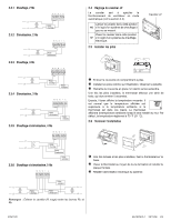
Identify and label each wire (with the corresponding letter on
the wire terminal) and remove them from the terminals.
If necessary, strip the end of each wire (maximum of 1/4 inch).
Wrap the wires around a pencil to prevent
them from falling into the wall.
If the hole in the wall is too big, insulate it
using a non-flammable material in order
to avoid air draughts behind the thermo-
stat.
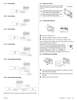
2.2
Installing the New Baseplate
For a new installation, choose a location approximately 5 feet
(1.5 m) above the floor and on an inside wall. Avoid draughty
areas (top of staircase, air outlet, etc.), dead air spots (behind
doors), direct sunlight or areas near concealed pipes or chim-
neys.
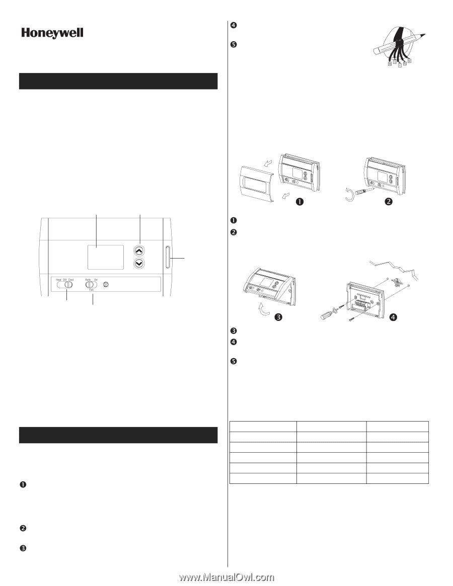
Remove the thermostat faceplate.
Loosen the locking screw to separate the thermostat from its
baseplate (the screw cannot be completely removed).
Tilt the thermostat upwards.
Mark and bore the appropriate mounting holes (using a 3/16”
drill bit) or use the existing holes. Insert the plastic anchors.
Pass the wires through the opening of the baseplate and fix the
baseplate to the wall using the screws provided.
2.3
Connecting the Thermostat
Refer to the following table for matching the wire labels with the
thermostat terminals.
Note
: Do not connect wires identified as C, X or B. Wrap the bare
end of these wires with electrical tape.
Important
: The red jumper wire between Rh and Rc terminals must
be removed in a 5-wire installation.
1. Introduction
2. Installation
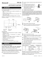
RTH1120
Non-programmable Electronic Thermostat
Installation and User Guide
Display
Adjustment
buttons
System operating
mode selector
Fan operating
mode selector
Backlight
button
RTH1120 terminals
Description
Wire labels
Rh
Heating power supply
Rh, R, 4, V
Rc
Cooling power supply
Rc, R
W
Heating signal
W, W1, H
Y
Cooling signal
Y, Y1, M
G
Fan
G, F