Honeywell RTH1120 Owner's Manual - Page 3
Basic Functions, Configuration Menu, Technical Specifications
 |
View all Honeywell RTH1120 manuals
Add to My Manuals
Save this manual to your list of manuals |
Page 3 highlights
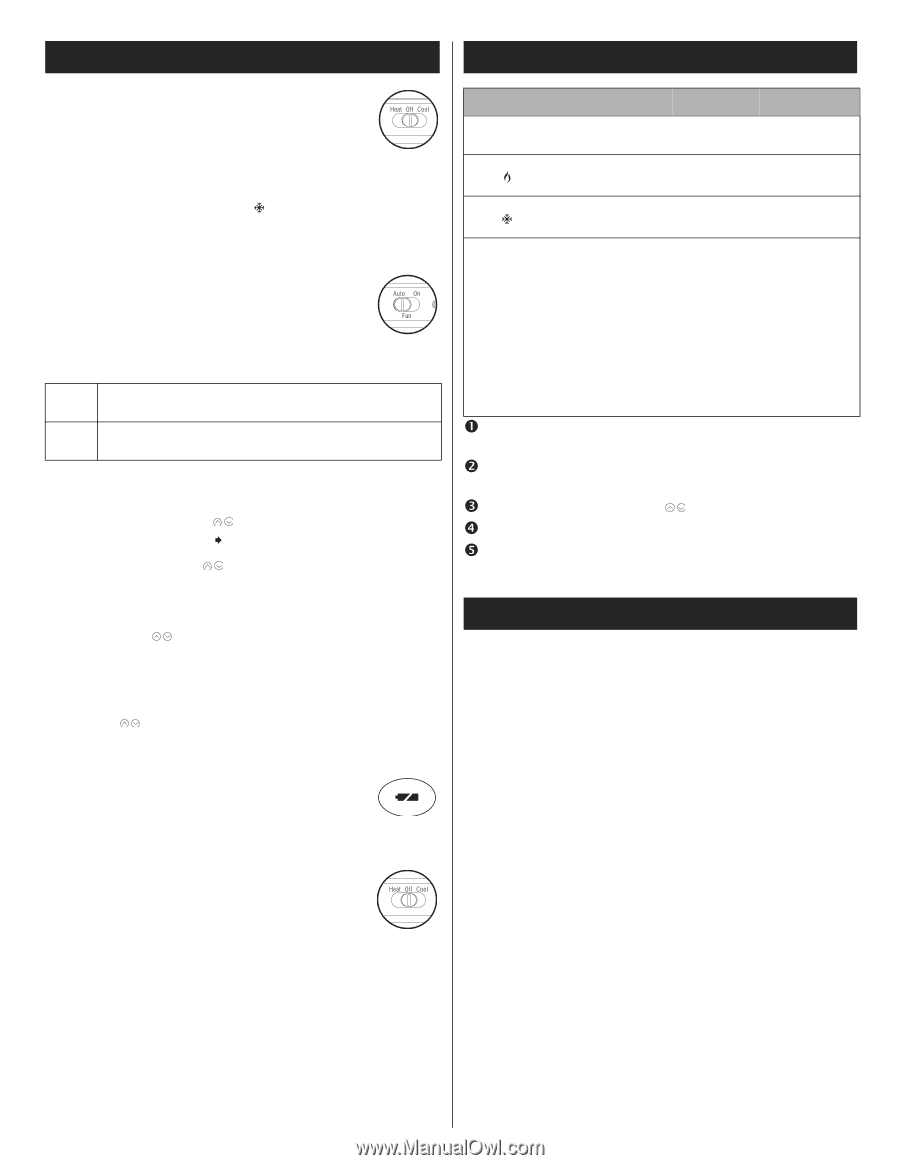
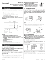
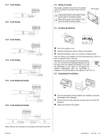
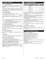
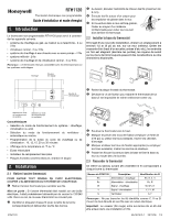
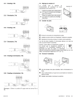
3. Basic Functions 4. Configuration Menu 3.1 System Operating Mode Use the selector switch to place the system in Heating mode (HEAT) or Cooling mode (COOL), or to turn the system off. Note: When you place the thermostat in Cooling mode, you might need to wait up to five minutes before cooling can start. This is a safety feature for the compressor. will flash on the screen until cooling can start again. 3.2 Fan Operating Mode Use the selector switch to set the fan to automatic mode (AUTO) or continuous mode (ON). Note: This switch is not used if you have a 2-wire installation as the fan is not connected to the thermostat. AUTO The fan operates only when the heating or cooling system is On (typical setting). ON The fan operates continuously. Use this setting to improve air circulation and air cleaning. 3.3 Displaying the Temperature The actual temperature is normally displayed. To view the setpoint, press once on either of the buttons. The setpoint is displayed for 5 seconds along with the icon. Note: Pressing any of the the setpoint. buttons more than once will change 3.4 Setting the Temperature Press one of the played. buttons until the desired temperature is dis- 3.5 Backlight The display illuminates for 12 seconds when the backlight button or either of the buttons is pressed. 3.6 Battery Replacement Indicator An icon appears when the batteries need replacement. This icon will flash for 120 days, then the thermostat will cut power to the heating/cooling unit. The icon disappears once the batteries are replaced. The temperature settings are saved and do not need to be re-entered. Warning: Before removing the batteries, place the system switch on the thermostat to Off. Otherwise, the heating/cooling unit might still be running even after the batteries are removed. DISPLAY DESCRIPTION DEFAULT SETTINGS Temperature display Heating cycles per hour 1 Cooling cycles per hour 1 °F °C or °F 4 2, 3, 4, 5 or 6 2 4 2, 3, 4, 5 or 6 3 1 When either the heating or cooling parameter is displayed, use the system mode selector switch to alternate between the two parameters. 2 For optimal heating control, use the setting that matches your system as follows: 2=30 min (steam or gravity), 3=20 min (hot water or 90%+ high-efficiency furnace), 4=15 min (gas or oil), 5=12 min (alternate setting for gas or oil), 6=10 min (electric). 3 The corresponding cooling cycle lengths are as follows: 2=30 min, 3=20 min, 4=15 min, 5=12 min, 6=10 min. n To access the configuration menu, press the backlight button for 3 seconds. o To go to the next parameter (menu item), briefly press the back- light button. p To modify a parameter, press . q Repeat steps 2 and 3 if necessary. r Press the backlight button for 3 seconds to exit the configura- tion menu. 5. Technical Specifications Power supply: 2 AA batteries Maximum load: 1 A @ 24 Vac per output Setpoint range (heating): 41 to 82°F (5 to 28°C) Setpoint range (cooling): 59 to 95°F (15 to 35°C) Display range: 23 to 122°F (-5 to 50°C) Storage temperature: -2 to 122°F (-20 to 50°C) Temperature display resolution: 1°F (0.5°C) Accuracy: ± 1°F (0.5°C) Heating/cooling cycle lengths: 10, 12, 15, 20 or 30 minutes (programmable) Compressor short-cycle protection (minimum off time): 5 minutes Data memory: non-volatile Dimensions: 5 in. x 3 in. x 1 in. (127 mm x 75 mm x 28 mm) RTH1120 69-1875EF-1 29/11/06 3/4
-
 1
1 -
 2
2 -
 3
3 -
 4
4 -
 5
5 -
 6
6 -
 7
7 -
 8
8
 |
 |