Honeywell T4398A1021 User Guide - Page 3
Recycling Notice, Warning, Caution - installation
 |
UPC - 085267088442
View all Honeywell T4398A1021 manuals
Add to My Manuals
Save this manual to your list of manuals |
Page 3 highlights
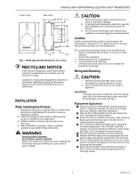
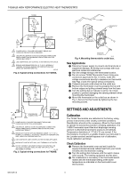
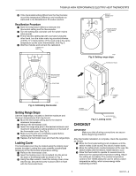
T4398A,B HIGH PERFORMANCE ELECTRIC HEAT THERMOSTATS FRONT VIEW 80 • 70 • 60 • 50 • ˚F SIDE VIEW 1-3/4 (48) 3/4 (19) 1/2 (13) 4-3/8 (111) 2-1/8 (54) 3-1/4 (83) 2-7/8 (73) 1-1/2 (39) 1/2 (13) M5795A Fig. 1. T4398 approximate dimensions in in. (mm). RECYCLING NOTICE If this control is replacing a control that contains mercury in a sealed tube, do not place your old control in the trash. Contact your local waste management authority for instructions regarding recycling and the proper disposal of any control containing mercury in a sealed tube. INSTALLATION When Installing this Product... 1. Read these instructions carefully. Failure to follow these instructions could damage the product or cause a hazardous condition. 2. Check the ratings on the product to make sure the product is suitable for your application. 3. Installer must be a trained, experienced service technician. 4. After installation is complete, check out product operation as provided in these instructions. WARNING HIGH VOLTAGE CONTROL. ELECTRICAL SHOCK HAZARD. Follow local codes and ordinances when installing this thermostat. Improper handling can cause serious injury or death. CAUTION 1. Disconnect power supply to prevent electrical shock or equipment damage. 2. If connecting with aluminum conductors, use CO/ ALR solderless wire connectors to avoid fire hazard. 3. Do not remove thermostat cover until wiring is complete to avoid damaging the sensing element. Location Install a vertical outlet box, which is used to mount the thermostat on, about 5 ft (1.5 m) above the floor in an area with good air circulation at room temperature. Do not install the thermostat where it may be affected by: - drafts or dead spots behind doors, in corners or under cabinets. - hot air from convectors. - radiant heat from sun or appliances. - concealed pipes and chimneys. - unheated (uncooled) areas such as an outside wall behind the thermostat. Wiring and Mounting CAUTION 1. Handle the thermostat with care to avoid damaging the sensing element or control. 2. Use a separate limit control in the heating appliance. IMPORTANT If locking cover feature is desired, insert the locking cover clip in the thermostat base before mounting the thermostat on the wall. See Fig. 7. Replacement Applications ᕡ Disconnect power to thermostat to prevent electrical shock or equipment damage. All wiring must comply with local electrical codes and ordinances. ᕢ Remove the old thermostat from the wall, taking care not to damage the wiring insulation. ᕣ Check the old wire insulation for cracks, nicks or fraying. Apply approved electrical tape to insulate wires or replace wires as necessary. ᕤ Do not remove T4398 Thermostat Cover. Using wire connectors approved for No. 12 wires, make line voltage connections directly to leadwires on thermostat. See Figs. 2 and 3 for typical wiring connections. ᕥ Prebend and push solid wires into the outlet box. ᕦ Remove the thermostat cover by grasping the top and bottom edges and pulling outward away from the base. ᕧ Turn the setting dial so the indicator is at the 12 o'clock position to prevent damaging the sensing element when mounting the thermostat. ᕨ Mount the thermostat on the outlet box as shown in Fig. 4. Secure the thermostat by tightening the two mounting screws. 3 68-0147-2
-
 1
1 -
 2
2 -
 3
3 -
 4
4 -
 5
5 -
 6
6 -
 7
7 -
 8
8
 |
 |
