Honeywell T4398A1021 User Guide - Page 4
Settings And Adjustments - wiring
 |
UPC - 085267088442
View all Honeywell T4398A1021 manuals
Add to My Manuals
Save this manual to your list of manuals |
Page 4 highlights
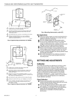
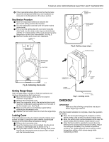
T4398A,B HIGH PERFORMANCE ELECTRIC HEAT THERMOSTATS T4398A L1 4 T1 1 L1 (HOT) L2 SOLDERLESS CONNECTORS 2 ELECTRIC HEATER 3 1 POWER SUPPLY. PROVIDE DISCONNECT MEANS AND OVERLOAD PROTECTION AS REQUIRED. 2 USE SPECIAL SERVICE CO/ALR SOLDERLESS CONNECTORS WHEN CONNECTING ALUMINUM CONDUCTORS OR A FIRE HAZARD MAY RESULT. 3 USE A SEPARATE LIMIT CONTROL IN THE HEATING APPLIANCE. 4 BREAKS AND REMAKES BELOW -31°F (-35°C); NORMALLY THERMAL ACTIVATED. BREAKS ON TEMPERATURE RISE; MAKES ON TEMPERATURE FALL. M5791B Fig. 2. Typical wiring connections for T4398A. T4398B L1 3 L2 5 T1 T2 RED WIRE 6 ELECTRIC HEATER L2 1 SOLDERLESS CONNECTORS 4 L1 2 (HOT) 1 POWER SUPPLY. PROVIDE DISCONNECT MEANS AND OVERLOAD PROTECTION AS REQUIRED. 2 USE SPECIAL SERVICE CO/ALR SOLDERLESS CONNECTORS WHEN CONNECTING ALUMINUM CONDUCTORS OR A FIRE HAZARD MAY RESULT. 3 BREAKS AT POSITIVE OFF AND REMAKES UNDER -31°F (-35°C); NORMALLY THERMALLY ACTIVATED. BREAKS ON TEMPERATURE RISE; MAKES ON TEMPERATURE FALL. 4 USE A SEPARATE LIMIT CONTROL IN THE HEATING APPLIANCE. 5 BREAKS AT POSITIVE OFF ONLY; NOT THERMALLY ACTIVATED. 6 DO NOT CONNECT GROUNDED CONDUCTOR (NEUTRAL) ON 120 OR 227V CIRCUITS. INSULATE AND TAPE OR CUT OFF RED WIRES IF UNUSED. M5792B Fig. 3. Typical wiring connections for T4398B. WALL THERMOSTAT BASE OUTLET BOX SETTING DIAL INDICATOR 80 75 65 60 55 50 70 MOUNTING SCREWS (2) M5797 Fig. 4. Mounting thermostat to outlet box. New Applications ᕡ Disconnect power supply to prevent electrical shock or equipment damage. All wiring must comply with local electrical codes and ordinances. ᕢ Run line voltage wiring to the thermostat location. ᕣ Do not remove T4398 Thermostat Cover. Using wire connectors approved for No. 12 wires, make line voltage connections directly to leadwires on thermostat. See Figs. 2 and 3 for typical wiring connections. ᕤ Prebend and push solid wires into the outlet box. ᕥ Remove the thermostat cover by grasping the top and bottom edges and pulling outward away from the base. ᕦ Turn the setting dial so indicator is at the 12 o'clock position to prevent damaging the sensing element when mounting the thermostat. ᕧ Mount the thermostat on the outlet box as shown in Fig. 4. Secure the thermostat by tightening the two mounting screws. SETTINGS AND ADJUSTMENTS Calibration The T4398 Thermostats are calibrated at the factory using precise instruments under closely controlled conditions. Recalibration should not be necessary. Allow the thermostat to operate for several hours before checking calibration. The T4398 Thermostat vapor-filled dual diaphragm sensing element is affected by barometric pressure and altitude. Temperature deviations of 1°F (0.5°C) are normal. If the thermostat is mounted in a suitable location (as instructed in the Location section) and still appears out of calibration, check calibration as follows. Check Calibration ᕡ Remove the thermostat cover and set it aside for several minutes because radiant heat from your hands will affect the thermometer reading. ᕢ Turn the setting dial clockwise until the switch makes (click sound). The heating equipment and fan start. ᕣ No recalibration is necessary if the thermostat switch makes with the thermostat setting at the same temperature as indicated on the thermostat cover thermometer. 68-0147-2 4
-
 1
1 -
 2
2 -
 3
3 -
 4
4 -
 5
5 -
 6
6 -
 7
7 -
 8
8
 |
 |
