Honeywell T8195B Installation Instructions - Page 4
Mount The Thermostat, Insert Timer Batteries Optional, Set Timer, Attach Thermostat Cover - wiring
 |
View all Honeywell T8195B manuals
Add to My Manuals
Save this manual to your list of manuals |
Page 4 highlights
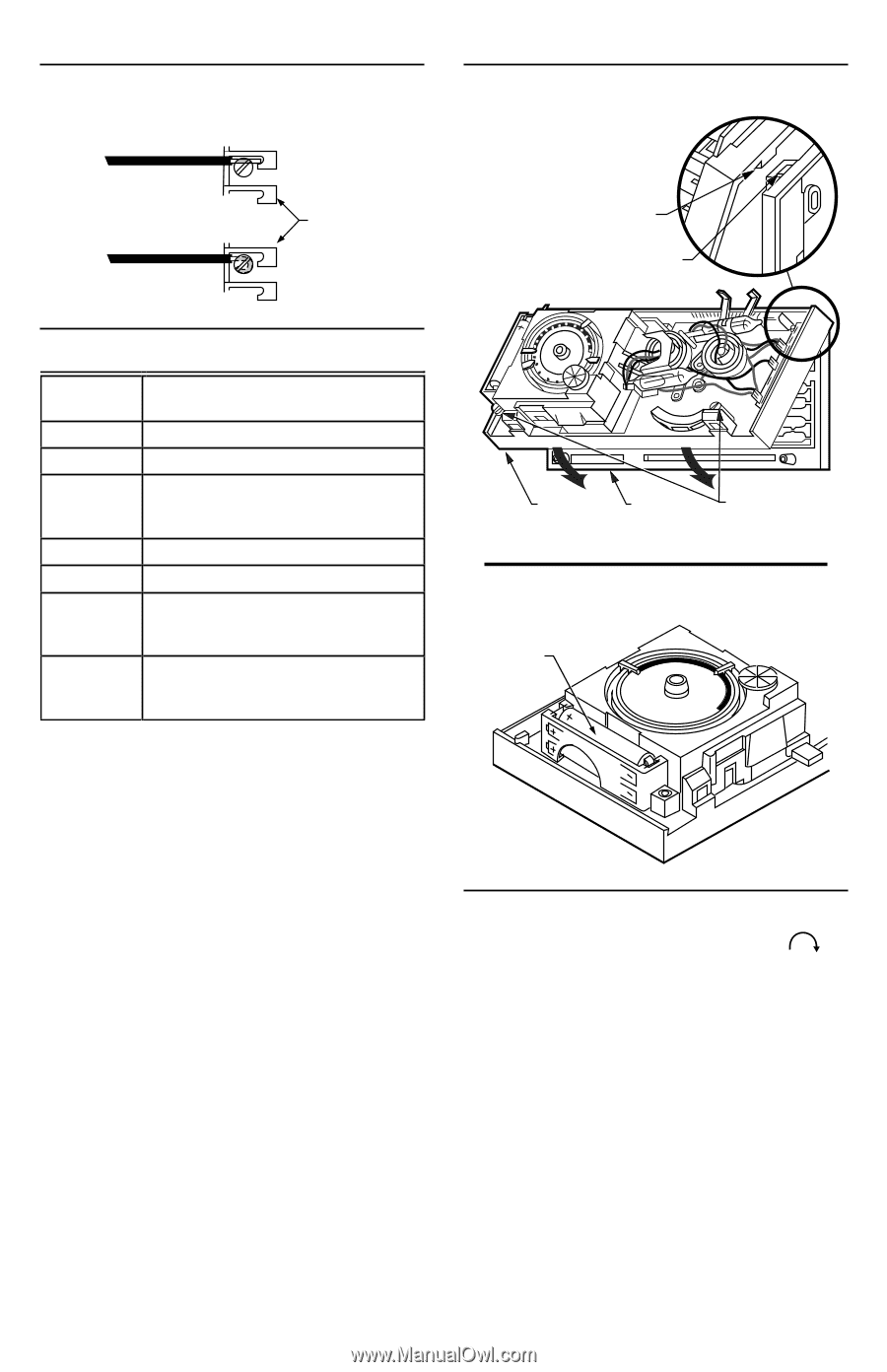
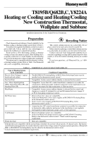
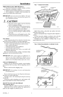
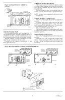
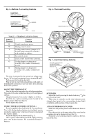
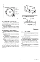
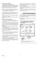
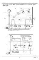
Fig. 5-Methods of connecting terminals. FOR STRAIGHT CONNECTION- STRIP 5/16 in. [8 mm] Fig. 6-Thermostat mounting. FOR WRAPAROUND CONNECTION- STRIP 7/16 in. [11 mm] BARRIER M1556B TABLE 2-TERMINAL DESIGNATIONS. Subbase Terminal Control Function R Control transformer power. W Heating control circuit. Y Cooling control circuit; jumper to W for heat pump compressor control if no P terminal on subbase. G Fan control circuit. C Clock control (transformer common). O Cooling damper or changeover/ reversing valve, makes continuously in cool. B Heating damper or changeover/ reversing valve, makes continuously in heat. The timer is powered by the system low-voltage transformer. 24 Vac must be maintained across terminals R and C. Push excess wire back into the wall. Plug the hole in wall with nonhardening caulk, putty, or nonflammable insulation to prevent drafts from affecting thermostat operation. MOUNT THE THERMOSTAT Note the tabs on the top inside edge of the thermostat base. These tabs fit the slots molded into the top of the wallplate or subbase. Hang the thermostat base on the wallplate or subbase. Insert the two captive mounting screws located in the bottom corners of the base (Fig. 6). Firmly tighten the screws. INSERT TIMER BATTERIES (OPTIONAL) Power is supplied to the clock by the 24-Vac transformer. Two AAA alkaline backup batteries (not included) may be installed to supply power to the timer if power is interrupted due to power failure. Install the batteries in the thermostat (Fig. 7). Once a year or when batteries are dead, replace with two new AAA alkaline batteries. We recommend Energizer® batteries. TAB (2) MOUNTING SLOT (2) 4 3 2 1 12 5 9 8 76 11 10 9 8 7 10 12 11 6 THERMOSTAT BASE WALLPLATE OR SUBBASE CAPTIVE MOUNTING SCREWS M8603 Fig. 7-Insert timer backup batteries. BATTERY LOCATION FOR (2) AAA BATTERIES; INSTALL WITH POSITIVE ENDS UP M8585 SET TIMER Adjust the clock by moving the knob clockwise . Do not reverse the knob. When time is correctly set, the time indicator arrow (triangle shape) points to the corresponding daytime (light) or nighttime (dark) portion of the program dial. ATTACH THERMOSTAT COVER Make sure the packing inserts in the thermostat base are removed. Place the two tabs on the upper edge of the cover into the mounting slots in the thermostat base (Fig. 9). Swing the cover downward until it catches at the bot- tom of the base. 69-0564-3 4
-
 1
1 -
 2
2 -
 3
3 -
 4
4 -
 5
5 -
 6
6 -
 7
7 -
 8
8
 |
 |