Honeywell T8195B Installation Instructions - Page 6
Typical Wiring Diagrams - troubleshooting
 |
View all Honeywell T8195B manuals
Add to My Manuals
Save this manual to your list of manuals |
Page 6 highlights
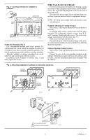
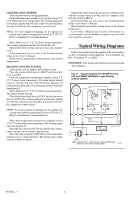
COOLING-ONLY SYSTEM Turn on power to the cooling equipment. Push both temperature setting levers together at least 5° F [3° C] below the room temperature. The cooling equipment will operate, and the fan will start. Allow for any time delay that may be built into the compressor control circuit. NOTE: To avoid compressor damage, do not operate the system when outdoor temperature is below 50° F [10° C]. Refer to manufacturer recommendations. Move both levers 5° F [3° C] above room temperature. The cooling equipment and the fan should shut off. Operate the entire cooling system at least one complete cycle. If thermostat fails any test, refer to the Troubleshooting Guide in the Owner's Manual. Reset both the temperature setting levers to the desired temperatures. HEATING/COOLING SYSTEM Turn on power to the furnace and cooling system. Place the system switch lever to HEAT and fan switch lever to AUTO. Push both temperature setting levers together at least 5° F [3° C] above room temperature. The main burner should come on. The fan will start when the furnace heats up. (If central electric heat, fan coil or heat pump system, fan starts immediately.) Move both levers 5° F [3° C] below room temperature. The burner should shut off. Place the system switch lever to COOL and the fan switch lever to AUTO. The cooling equipment will operate, and the fan will start. Allow for any time delay that may be built into the compressor control circuit. NOTE: To avoid compressor damage, do not operate the system when outdoor temperature is below 50° F [10° C]. Refer to manufacturer recommendations. Move both temperature setting levers together at least 5° F [3° C] above the room temperature. The cooling equipment should shut off. Place the fan switch to ON. The fan should run continuously with the system switch in any position. Place the system switch to OFF. Move both temperature setting levers to various positions. The heating and cooling systems should not operate. Operate the entire system for at least one complete cycle with the system switch at COOL and one complete cycle with the switch at HEAT. If thermostat fails any test, refer to the Troubleshooting Guide in the Owner's Manual. Reset both the temperature setting levers to the desired temperatures. Leave Owner's Manual and Assistance Information in a convenient place for the building occupant or provide with other appliance manuals. Typical Wiring Diagrams Follow the hookup diagram supplied with your heating, cooling, or heating/cooling equipment. If not available, use Figs. 11 through 13 as a guide. REMEMBER: Your wiring must follow local electrical codes and ordinances. Fig. 11-Typical hookup for T8195B Thermostat and Q682C Wallplate in gas heating control system. TIMER THERMOSTAT H FALL C HEAT ANTICIPATOR H C FALL HEAT ANTICIPATOR COOL C R ANTICIPATOR W Y L1 (HOT) L2 1 GAS CONTROL WALLPLATE 1 POWER SUPPLY. PROVIDE DISCONNECT MEANS AND OVERLOAD PROTECTION AS REQUIRED. M503A 69-0564-3 6
-
 1
1 -
 2
2 -
 3
3 -
 4
4 -
 5
5 -
 6
6 -
 7
7 -
 8
8
 |
 |