Honeywell TB7980B1005 Installation Guide - Page 3
Configuration - thermostat
 |
View all Honeywell TB7980B1005 manuals
Add to My Manuals
Save this manual to your list of manuals |
Page 3 highlights
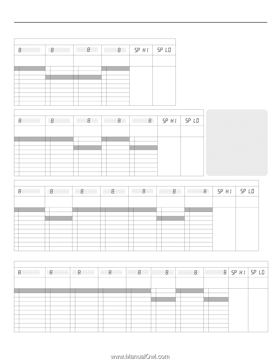
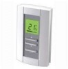
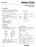
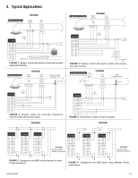
4. Configuration 4.1 Configuration Menus (See following pages for explanations) NOTE: Factory settings are inside the shaded cells. TB7980A model 1. Remove the thermostat from its base and set the SW2 switch to MENU. Application (section 4.2) 0 Internal sensor 1 Room 2 Return 3 Supply 4 Auto changeover 5 Limited cooling Default mode & Output 1 type (section 4.3.1) 0 Cool / 0-10V 1 Heat / 0-10 V 2 Cool / 2-10 V 3 Heat / 2-10 V NSB value (section 5.6) 1 2°F (1°C) 2 4°F (2°C) 3 6°F (3°C) 4 8°F (4°C) 5 10°F (5°C) 6 12°F (6°C) 7 14°F (7°C) 8 16°F (8°C) 9 18°F (9°C) Output 1 min. opening (section 4.3.2) 0 0% 1 10% 2 20% 3 30% 4 40% 5 50% Maximum setpoint (section 4.6) Minimum setpoint (section 4.6) 2. Reinstall the thermostat. The thermostat is now in configuration mode. The first digit flashes to indicate that the first item of the menu can now be modified. Can be set between 95°F Can be set between 50°F 3. To modify the setting, use the up/down arrows. Refer to the adjacent tables. (35°C) and ''minimum setpoint + 1'' (10°C) and ''maximum setpoint - 1'' 4. Press Override to save the new setting and go to the next item. Default value Default value 5. Repeat steps 3 and 4 for remaining items. is 95°F (35°C) is 50°F (10°C) 6. When the configuration is done, set the SW2 switch back to NORMAL. TB6980A model Application (section 4.2) 0 Internal sensor 1 Room 2 Return 3 Supply 4 Auto changeover 5 Limited cooling Default mode (section 4.3.1) 0 Cool 1 Heat NSB value (section 5.6) 1 2°F (1°C) 2 4°F (2°C) 3 6°F (3°C) 4 8°F (4°C) 5 10°F (5°C) 6 12°F (6°C) 7 14°F (7°C) 8 16°F (8°C) 9 18°F (9°C) Output 1 min. opening (section 4.3.2) 0 0% 1 10% 2 20% 3 30% 4 40% 5 50% Output 1 opening time (section 4.3.3) 0 80 1 90 2 100 3 110 4 120 5 130 6 140 7 150 8 160 Maximum setpoint (section 4.6) Minimum setpoint (section 4.6) Can be set between 95°F (35°C) and ''minimum setpoint + 1'' Can be set between 50°F (10°C) and ''maximum setpoint - 1'' Default value Default value is 95°F (35°C) is 50°F (10°C) ABBREVIATIONS NSB - Night setback (number of degrees the thermostat will be set back upon receiving a setback signal) SSR - Solid state relay (used with fast cycling electric heaters, SSR's are a quiet alternative to electromechanical relays. They're typically included with electric duct reheat equipment) SCR - Silicon controlled rectifier (similar to an SSR, SCR's are also quiet and capable of switching very high current. If used, they're usually included with the equipment) N.C. - Normally closed N.O. - Normally open TB7980B model Application (section 4.2) 0 Internal sensor 1 Room 2 Return 3 Supply 4 Auto changeover 5 Limited cooling Default mode & Output 1 type (section 4.3.1) 0 Cool / 0-10V 1 Heat / 0-10 V 2 Cool / 2-10 V 3 Heat / 2-10 V Output 2 typea (section 4.4) 0 Not used 1 SSR 24 VAC 2 N.C. Valve 3 N.O. Valve 4 Mech. relay 5 SSR 3-32 V 6 SCR 0-10 V 7 Act. 0-10 V 8 Act. / 2-10 V Output 3 type (section 4.5) 0 Not used 1 SSR 24 VAC 2 N.C. Valve 3 N.O. Valve 4 Mech. relay 5 Contact Output 3 activation (section 4.5) 0 100% 1 10% 2 20% 3 30% 4 40% 5 50% 6 60% 7 70% 8 80% 9 90% NSB value (section 5.6) 1 2°F (1°C) 2 4°F (2°C) 3 6°F (3°C) 4 8°F (4°C) 5 10°F (5°C) 6 12°F (6°C) 7 14°F (7°C) 8 16°F (8°C) 9 18°F (9°C) Output 1 min. opening (section 4.3.2) 0 0% 1 10% 2 20% 3 30% 4 40% 5 50% a. If Output 2 type is set to 0-4, set the SW6 switch to Triac. If the output type is set to 5-8, set the switch to Analog (see section 4.7). Maximum setpoint (section 4.6) Minimum setpoint (section 4.6) Can be set between 95°F (35°C) and ''minimum setpoint + 1'' Can be set between 50°F (10°C) and ''maximum setpoint - 1'' Default value Default value is 95°F (35°C) is 50°F (10°C) TB6980B model Application (section 4.2) 0 Internal sensor 1 Room 2 Return 3 Supply 4 Auto changeover 5 Limited cooling Default mode (section 4.3.1) 0 Cool 1 Heat Output 2 typea (section 4.4) 0 Not used 1 SSR 24 VAC 2 N.C. Valve 3 N.O. Valve 4 Mech. relay 5 SSR 3-32 V 6 SCR 0-10 V 7 Act. 0-10 V 8 Act. / 2-10 V Output 3 type (section 4.5) 0 Not used 1 SSR 24 VAC 2 N.C. Valve 3 N.O. Valve 4 Mech. relay 5 Contact Output 3 activation (section 4.5) 0 100% 1 10% 2 20% 3 30% 4 40% 5 50% 6 60% 7 70% 8 80% 9 90% NSB value (section 5.6) 1 2°F (1°C) 2 4°F (2°C) 3 6°F (3°C) 4 8°F (4°C) 5 10°F (5°C) 6 12°F (6°C) 7 14°F (7°C) 8 16°F (8°C) 9 18°F (9°C) Output 1 min. opening (section 4.3.2) 0 0% 1 10% 2 20% 3 30% 4 40% 5 50% a. If Output 2 type is set to 0-4, set the SW6 switch to Triac. If the output type is set to 5-8, set the switch to Analog (see section 4.7). Output 1 opening time (section 4.3.3) 0 80 1 90 2 100 3 110 4 120 5 130 6 140 7 150 8 160 Maximum Minimum setpoint setpoint (section 4.6) (section 4.6) Can be set between 95°F (35°C) and ''minimum setpoint + 1'' Can be set between 50°F (10°C) and ''maximum setpoint - 1'' Default Default value is 95°F value is 50°F (35°C) (10°C) TB6980/TB7980 3/6
-
 1
1 -
 2
2 -
 3
3 -
 4
4 -
 5
5 -
 6
6
 |
 |