Hotpoint RGA724EKWH Installation Instructions - Page 28
Flexible Connector, Rigid Pipe Hookup, Hookup, Recommended Gas And Electric Supply Location
 |
UPC - 084691131717
View all Hotpoint RGA724EKWH manuals
Add to My Manuals
Save this manual to your list of manuals |
Page 28 highlights
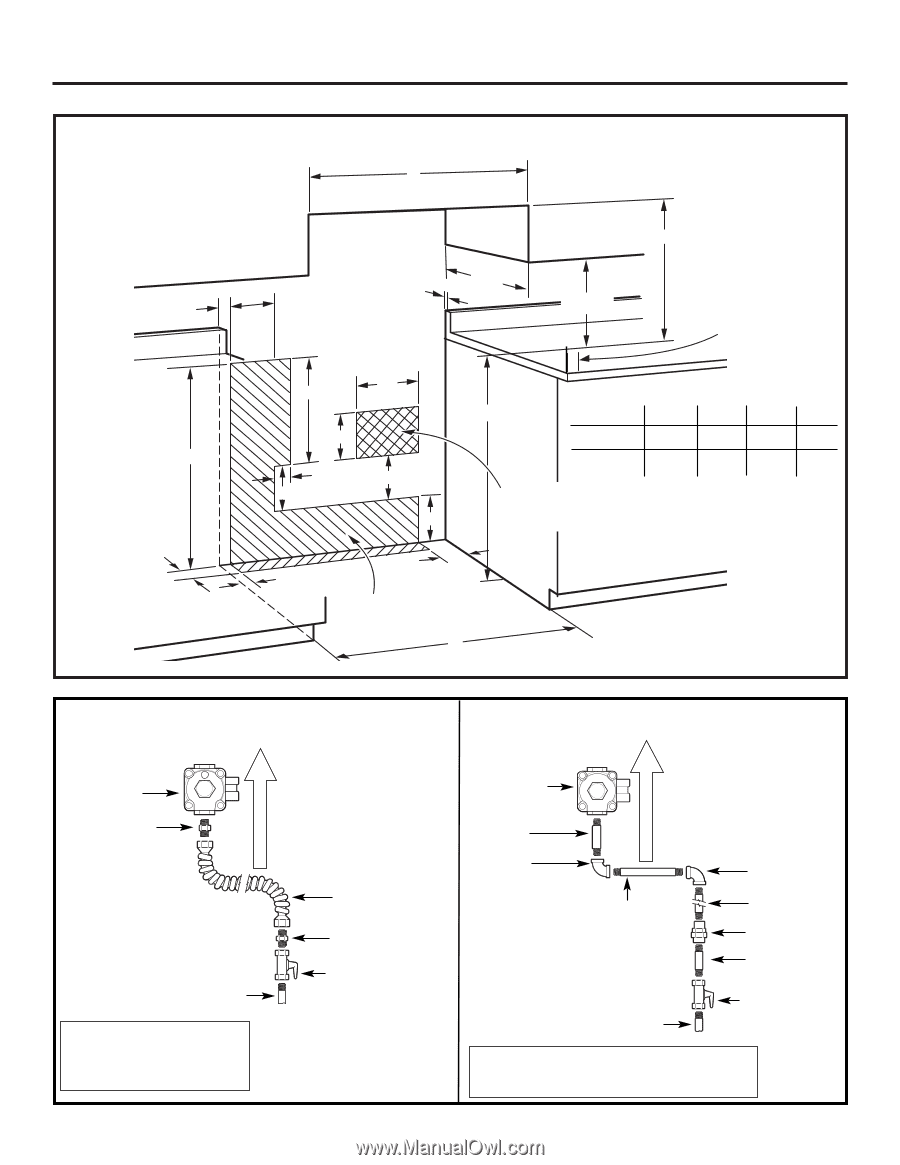
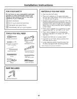
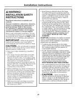
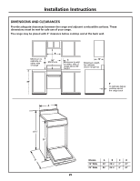
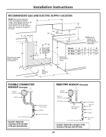
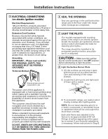
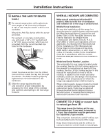
Installation Instructions RECOMMENDED GAS AND ELECTRIC SUPPLY LOCATION NOTE: Recommended gas hook-up locations behind range. Gas fittings and shut-off cock should NOT protrude more than 2″ from the wall to allow the range to fit against the wall. C D A 13″ 1/4″ Max 18″ Min. 30″ Min. 30″ Check local codes before making connections. 12″ 14″ 8″ 3″ 8″ 8″ 8″ 36″ Models 20″ Wide 24″ Wide Electrical Connection Area A 203⁄8″ 243⁄8″ B Minimum distance to walls above the cooktop on each side B C D 2″ 2″ 21⁄2″ 2″ 3″ 51⁄2″ 5″ 2″ 2″ Gas Hookup Area A FLEXIBLE CONNECTOR HOOKUP (Example) Pressure regulator Adapter 1/2″ or 3/4″ Gas pipe Installer: Inform the consumer of the location of the gas shut-off valve. Gas Flow into Range Gas Flow into Range RIGID PIPE HOOKUP (Example) Flex connector (41⁄2 ft. max.) Adapter Gas shut-off valve Pressure regulator Black iron pipe 41⁄2" 90° Elbow Nipple (may not be needed) 90° Elbow Black iron pipe Union Nipple 1/2″ or 3/4″ Gas pipe Gas shut-off valve Installer: Inform the consumer of the location of the gas shut-off valve. 28
-
 1
1 -
2
-
3
-
4
-
5
-
6
-
7
-
8
-
9
-
10
-
11
-
12
-
13
-
14
-
15
-
16
-
17
-
18
-
19
-
20
-
21
-
22
-
 23
23 -
 24
24 -
 25
25 -
 26
26 -
 27
27 -
 28
28 -
 29
29 -
 30
30 -
 31
31 -
 32
32 -
 33
33 -
34
-
35
-
36
 |
 |