Hunter 21325 Owner's Manual
Hunter 21325 Manual
 |
View all Hunter 21325 manuals
Add to My Manuals
Save this manual to your list of manuals |
Hunter 21325 manual content summary:
- Hunter 21325 | Owner's Manual - Page 1
For Your Records and Warranty Assistance For reference, also attach your receipt or a copy of your receipt to the manual. Model Name Model No. Date Purchased Where Purchased Type 2 Models Owner's Guide and Installation Manual English Español Form# 45037-01 20110606 ©2011 Hunter Fan Co. - Hunter 21325 | Owner's Manual - Page 2
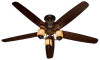
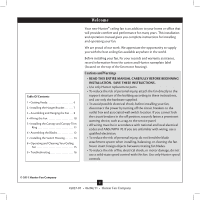
Cleaning Your Ceiling Fan 15 9 • Troubleshooting 16 Welcome Your new Hunter® ceiling fan is an addition to your home or office that will provide comfort and performance for many years. This installation and operation manual gives you complete instructions for installing and operating your fan. We - Hunter 21325 | Owner's Manual - Page 3
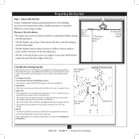
and safe for your new Hunter fan. If you cannot check off every item, prepare a new fan site as described on this page. Fan Support System • Fan attaches directly to building structure. • Fan support system will hold full weight of the fan and light kit. Ceiling Hole • The outlet box clearance - Hunter 21325 | Owner's Manual - Page 4
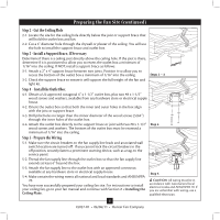
support service panel. 5-2. Thread the fan supply line through the outlet box so that the fan supply line extends at least 6" beyond the box. 5-3. Attach the fan ceiling fan site. For instructions to install your ceiling fan, go to your fan manual and continue with Section 2 • Installing the Ceiling - Hunter 21325 | Owner's Manual - Page 5
, follow the instructions included with each product. For quiet and optimum performance of your Hunter fan, use only Hunter speed controls. Support Brace Ceiling Outlet Box For ceilings higher than 8 feet, you can purchase Hunter extension downrods. All Hunter fans use sturdy 3/4" diameter - Hunter 21325 | Owner's Manual - Page 6
missing or damaged, contact your Hunter dealer or call Hunter Technical Support Department at 888-830-1326. Preparing the Fan Site Before you begin installing the fan, follow all the instructions in the pullout sheet called "Preparing the Fan Site." Proper ceiling fan location and attachment to the - Hunter 21325 | Owner's Manual - Page 7
wood support structure. For proper alignment use slotted holes directly across from each other. If you are installing the fan on an ANGLED ceiling, be Ceiling Peak Large Opening OR Steps 2-2 - 2-4 Ceiling Peak Large Opening LEFT Step 2-3 (Angled Ceiling Only) 7 45037-01 • 06/06/11 • Hunter Fan - Hunter 21325 | Owner's Manual - Page 8
the fan until you hear the notch pop into place.) Go to 4 • Wiring the Fan. Steps 3-4 - 3-5 WARNING: Fan may fall if not assembled as directed in these installation instructions. Downrod Canopy (with Washer) Canopy Trim Ring Setscrew Indent 8 45037-01 • 06/06/11 • Hunter Fan Company - Hunter 21325 | Owner's Manual - Page 9
. WARNING: Fan may fall if not assembled as directed in these installation instructions. Step 3-6 (Not Actual Size) Steps 3-8 - 3-9 Low Profile Washer Step 3-7 (Detail) Low Profile Washer Adapter Canopy Trim Ring #8-32 x 3/4" Screw Step 3-10 9 45037-01 • 06/06/11 • Hunter Fan Company - Hunter 21325 | Owner's Manual - Page 10
connectors upward and push them carefully back through the ceiling plate into the outlet box. 4-7. Spread the wires apart, with the grounded wires on one side of the outlet box and the ungrounded wires on the other side of the outlet box. Wire Connector 10 45037-01 • 06/06/11 • Hunter Fan Company - Hunter 21325 | Owner's Manual - Page 11
trim ring counter clockwise until it releases from canopy. Hanger Bracket Canopy Trim Ring Step 5-4 Step 5-3 Step 5-5 Canopy Screw 11 45037-01 • 06/06/11 • Hunter Fan Company - Hunter 21325 | Owner's Manual - Page 12
Blades Hunter fans use several styles of fan blade irons (brackets that hold the blade to the fan). 6-1. Your fan may include blade grommets. If your fan mounting screw through the blade iron, and attach lightly to the fan. Insert the second blade mounting screw, then securely tighten both mounting - Hunter 21325 | Owner's Manual - Page 13
switch housing fixture falling. Steps 7-1 - 7-4 Housing Assembly Screw Upper Switch Housing Plug Connector Lower Switch Housing Housing Assembly Screw 13 45037-01 • 06/06/11 • Hunter Fan Company - Hunter 21325 | Owner's Manual - Page 14
.Install three 14W CFL light bulbs Plug Connector Steps 7-5 - 7-6 Lower Switch Housing Housing Assembly Screw Plug Connector Detail Shade 14 45037-01 • 06/06/11 • Hunter Fan Company - Hunter 21325 | Owner's Manual - Page 15
draw air upward (clockwise blade rotation) will distribute the warmer air trapped at the ceiling around the room without causing a draft. 8-5. The blades on this fan have been treated with Hunter's Dust Armor protection, making the blades less likely to attract dust and dirt. Use a dry or slightly - Hunter 21325 | Owner's Manual - Page 16
screws. 3. Turn power off, support fan very carefully, and check that the hanger ball is properly seated. If you need parts or service assistance, please call 888‑830‑1326 (In Canada, call 866-268-1936) or visit us at our Web site at http://www.hunterfan.com. Hunter Fan Company 7130 Goodlett Farms
-
 1
1 -
 2
2 -
 3
3 -
 4
4 -
 5
5 -
 6
6 -
 7
7 -
8
-
9
-
10
-
11
-
12
-
13
-
14
-
15
-
16
 |
 |
Type 2 Models
Type 2 Models
Type 2 Models
Form# 45037-01
20110606
©2011 Hunter Fan Co.
For Your Records and
Warranty Assistance
For reference, also attach your receipt or a copy
of your receipt to the manual.
__________________________________________
Model Name
__________________________________________
Model No.
__________________________________________
Date Purchased
__________________________________________
Where Purchased
English
Español
Owner’s Guide and Installation Manual