Hunter 21325 Owner's Manual - Page 13
Turn the housing counterclockwise until the housing assembly
 |
View all Hunter 21325 manuals
Add to My Manuals
Save this manual to your list of manuals |
Page 13 highlights
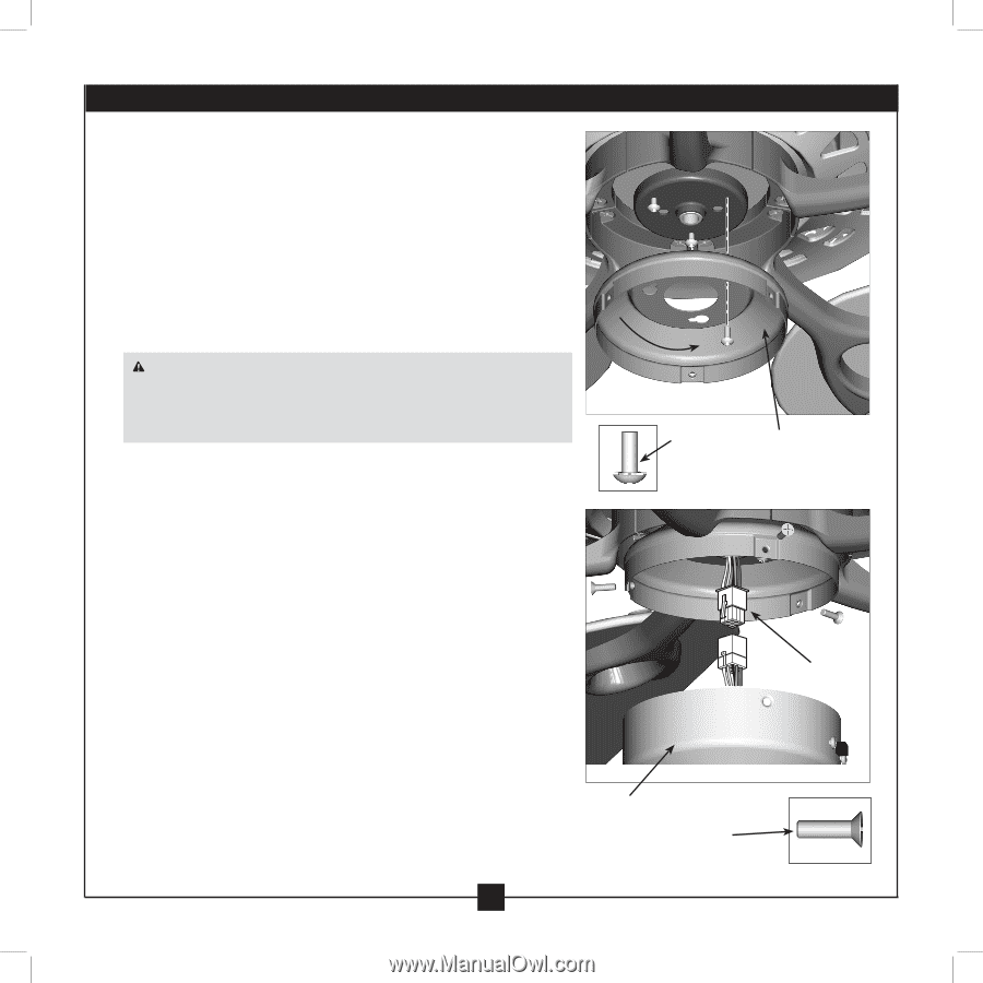
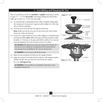
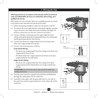
7 • Installing the Switch Housing 7-1. To attach the upper switch housing, partially install two housing assembly screws into the switch housing mounting plate. 7-2. Feed the upper plug connector through the center opening of the housing. 7-3. Align the keyhole slots in the housing with the housing assembly screws. 7-4. Turn the housing counterclockwise until the housing assembly screws are firmly situated in the narrow end of the keyhole slots. Install the remaining screw into the housing. Tighten all three screws firmly. CAUTION: Make sure the upper switch housing is securely attached to the switch housing mounting plate. Failure to properly attach and tighten all three assembly screws could result in the switch housing fixture falling. Steps 7-1 - 7-4 Housing Assembly Screw Upper Switch Housing Plug Connector Lower Switch Housing Housing Assembly Screw 13 45037-01 • 06/06/11 • Hunter Fan Company
-
 1
1 -
2
-
3
-
4
-
5
-
6
-
7
-
 8
8 -
 9
9 -
 10
10 -
 11
11 -
 12
12 -
 13
13 -
 14
14 -
 15
15 -
 16
16
 |
 |