Hunter 21585 Owner's Manual - Page 7
All wiring must be in accordance with national and local electrical, codes and ANSI/NFPA 70. If
 |
View all Hunter 21585 manuals
Add to My Manuals
Save this manual to your list of manuals |
Page 7 highlights
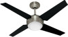
4 • Wiring the Fan All wiring must be in accordance with national and local electrical codes and ANSI/NFPA 70. If you are unfamiliar with wiring, use a qualified electrician. Wall switches are not included. Select an acceptable general-use switch in accordance with national and local electrical codes. 4-1. Before attempting installation, make sure the power is still off. 4-2. Place the receiver inside the canopy, making sure that the dipswitches and the oval shaped holes in the bottom of the receiver are facing down toward the bottom of the canopy. 4-3. Spread the receiver lead wires to each side and feed the wires from the top of the fan through the open slot in the receiver. 4-4. Place the receiver in the canopy. Make sure the slot in the receiver is aligned with the hook in the ceiling plate. 4-5. To connect the wires, hold the bare metal leads together and place a wire connector over them, then twist clockwise until tight. Using the small wire connectors, connect the fan to the receiver as follows: • Connect the yellow wire (ungrounded) from the fan to the yellow wire (ungrounded) from the receiver. • Connect the white wire (ungrounded) from the fan to the white wire (ungrounded) from the receiver (marked on white tag "LIGHT NEUTRAL OUT"). • Connect the pink wire (ungrounded) from the fan to the pink wire (ungrounded) from the receiver. • Connect the grey wire (ungrounded) from the fan to the grey wire (ungrounded) from the receiver. • Connect the black/white wire (ungrounded) from the fan to the black/white wire (ungrounded) from the receiver (marked on white tag "LIGHT LIVE OUT"). • Connect the red wire (ungrounded) from the fan to the red wire (ungrounded) from the receiver. Receiver A I H B G F C D E Step 4-7 A • Ground/Green Step 4-6 B • Receiver Black: "AC LIVE IN" • Ceiling Black C • Receiver White: "AC NEUTRAL IN" • Ceiling White Step 4-5 D • Fan Yellow • Receiver Yellow E • Fan White • Receiver White: "LIGHT NEUTRAL OUT" F • Fan Pink • Receiver Pink G • Fan Grey • Receiver Grey H • Fan Black/White • Receiver Black/White: "LIGHT LIVE OUT" I • Fan Red • Receiver Red Steps 4-5 - 4-7 Small Wire connector 7 42649-01 • 08/13/09 • Hunter Fan Company
-
 1
1 -
 2
2 -
 3
3 -
 4
4 -
 5
5 -
 6
6 -
 7
7 -
 8
8 -
 9
9 -
 10
10 -
 11
11 -
 12
12 -
13
-
14
-
15
 |
 |
