Hunter 21617 Owner's Manual - Page 11
separate side of the outlet box from the other wires.
 |
View all Hunter 21617 manuals
Add to My Manuals
Save this manual to your list of manuals |
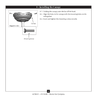
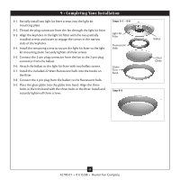
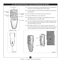
Page 11 highlights
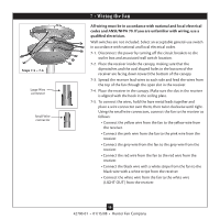
7-6. Using the large wire connectors, connect the fan and receiver to the power wires as follows: • Connect the white wire (A/C IN) from the receiver to the white wire from the ceiling. • Connect the black wire from the receiver to the black wire from the ceiling. CAUTION: Be sure no bare wire or wire strands are visible after making connections. 7-7. Run the thin white antenna wire from the receiver through one of the slots in the ceiling plate. (For best reception, make sure the end of the antenna is exposed at the top of the canopy.) 7-8. Connect the green ground wires from the ceiling plate and the downrod to the ground wire from the ceiling. 7-9. Push all wires and wire connectors back through the ceiling plate hole into the outlet box. Place the green and white wires on a separate side of the outlet box from the other wires. 11 42700-01 • 01/15/08 • Hunter Fan Company
-
 1
1 -
2
-
3
-
4
-
5
-
 6
6 -
 7
7 -
 8
8 -
 9
9 -
 10
10 -
 11
11 -
 12
12 -
 13
13 -
 14
14 -
 15
15 -
 16
16
 |
 |