Hunter 25866 Owner's Manual - Page 2
Downon Topof Fan
 |
View all Hunter 25866 manuals
Add to My Manuals
Save this manual to your list of manuals |
Page 2 highlights
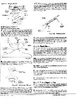
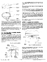
Step 4: Installation of Ceiling Plate A. install the (3) rubber bushings into the top of the ceiling plate by inserting small side of rubber bushing into the three round holes in the ceiling plate. See Figure 4. BRUUSBHBINEGR MOTE Figure.4. RubberBushings PCLEAILTIENG B. Thread the lead wires through the opening in the ceiling plate and install the ceiling plate to the 2X4 brace which supports the outlet box, Use (2)#10 wood screws 3" long and (2) flat washers for mounting. Drill (2) pilot holes for mounting screws 9/64" diameter. See Figure 4A, \\L7i- , Figure 4C. Assembling Top Housing ANOLANIRGARNDOARWPATNISEOERTDWCTIHTAHEBSSON TOP HOUSING O 0 O SLAOCSCRSEAEMTWIBOLNYS SVIHEOWW: LIONGOTKAINBGADNODWNONTOCNHTAOLPIGONFMFAENNT NOTE: Assembly Methods For Installer's Choice Hanging System Your New Hunter Fan can be hung in (2) different manners, one being as a low profile fan and also as a ball type hanging fan. Thus, Installer's Choice, Customers should read steps 5 through 7 and decide which style of mounting to use. ))Y' RBUUSBHBEINRG WFALSAHTER Figure 4A. Installing Ceiling Plate PCLEAILTIENG S3"CWREOWOD NOTE; When attaching ceiling plate to the outlet box support, make certain bushings remain in place. Step 5: Fan Assembly, Low Profile Version A. Place the canopy on top of the fan so the hole in the bottom of the canopy fits over the adaptor on the top of the fan. See Figure 5. place the canopy assembly washer inside the canopy with the vertical flange of the washer resting on the inside of the canopy. 8.32 SCREW WASASSHEEMRBLY CANOPY NOTE: Tighten the ceiling plate mounting screws only enough to provide slight compression of the bushings. Do not over-tighten. Step 4A: Assemble Top Housing Caution: Do Not Lift Motor By Wires. A. Assemble the housing to the hanger adapter using (3)#8- 32 screws, See figurer 4B and 4C. First align the (3) raised tabs on the hanger adaptorwith the (3) narrow notches in the top housing. Make certain the housing sits flat on top of the adaptor. Tighten the screws securely, CV) RHOOULEND ADAPTER Figure 5. Low Profile Version FAN OF B.Position the(3)slots in the canopy assembly washer over the (3) threaded holes in the adapter. See Figure 5. HOUOSPING #8 -32SCREW AHDAANPGTEERR C. Secure the canopy to the top of the fan using the (3) #832 X 3/4" long screws with lock washers. Make certain all screws are tight. Failure to do so could result in the fan falling. See Figure 5. Figure 4B. Assembling Top Housing Form No. 41128 11/93 MOTOR Caution: To ensure proper engagement of the canopy assembly screws, the canopy must fit snug against the top of the fan. Caution: Do not lift motor by wires. D. Being careful not to scratch the canopy finish, hang the fan from the hook in the ceiling plate using the round hole in the top of the canopy. See Figure 5 and 5A. 2 ©1993 Hunter Fan Co.Tm
-
 1
1 -
 2
2 -
 3
3 -
 4
4 -
 5
5 -
 6
6
 |
 |
