Hunter 25866 Owner's Manual - Page 3
Hanging, Version, Final, Wiring, Finish
 |
View all Hunter 25866 manuals
Add to My Manuals
Save this manual to your list of manuals |
Page 3 highlights
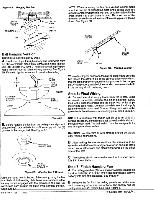
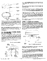
-I Figure 5A. Hanging The Fan GREEN GROUND -*- WIRE CONNECTOR FAN /" / CEILING PLATE HOOK CANOPY NOTE: When mounting the fan on a vaulted ceiling make sure that one set of enlongated slots in the ceiling plate are aligned vertically with the ceiling joist, or horizontally with the cross brace if a cross brace Is used, Be sure one of the threaded screw holes in the side of the ceiling plate is facing down. See Figure 5D. VAULTED CEILING Ball Hanging Version Caution: Do not lift motor by wires. A. Insert pipe nipple through canopy and feed wires from top of motor through pipe nipple. Screw pipe nipple into fan until tight (at least 4 1/2 turns). The setscrew locking the pipe nipple to motor must be tightened very securely. See Figure 5B. Failure to tighten screw could result in fan failing. t 6" MIN. LEAD WIRES PIPE NIPPLE BALL SCREW HOLE CEILING PLATE HOOK Figure 5D. Vaulted Ceiling When attaching the canopy to the ceiling plate make sure the two tabs in the center hole of the canopy align vertically so that the tabs properly engage the two grooves in the hanger ball. When properly installed, the round screw clearance hole in the canopy should be facing down. SET SCREW (TIGHTEN SECURELY) MOTOR CANOPY PIPE NIPPLE Step 6: Final Wiring A. Connect electrical supply leads from the motor, using approved connectors. Connect the black electrical supply lead to the black motor lead and the black with white stripe motor lead (see Note). Connect the white electrical supply lead to the white motor lead. Connect the ground wire to the green leads from the motor and ceiling plate. See Figure 5A. Figure 5B B. Before hanging the fan from the ceiling plate align and engage the (2) tabs in the bottom of the canopy with the (2) grooves in the hanger ball. See Figure 5C. CD GROOVE IN HANGER BALL NOTE: If a separate wall switch will be used to control a lighting accessory, connect the black wire with white stripe to the wall switch lead. The wall switch must be acceptable for use as a general use switch. CAUTION: No bare wire or wire strands should be visible after making connections. B. After making the wire connections, the wires should be spread apartwith thewhite and green wires on one side ofthe outlet box, and the black and black/white wires on the other side of the box. TAB IN BOTTOM OF CANOPY Figure 5C. Aligning Tab & Groove Using the round hole in the top of the canopy, hang the fan from the hook in the ceiling plate. Make sure both tabs in the canopy remain engaged with the grooves in the ball. Be careful and don't scratch the finish while hanging the fan. See figure_5A__ FormN(5741128- 11793 C. The splices should be turned upward and pushed carefully into the outlet box. Step 7: Finish Hanging Fan A. The ceiling plate has (3)mounting screw holes located on the side, Install (2) #10-32 X 1/2" Phillips round head screws halfway into two of these holes. See Figure 6. B. Remove the fan from the ceiling plate hook. Make sure not to break any of the wire connections. The canopy has (2) mating-slots and (1) mating hole. See Figure 6. 01993 HUhler
-
 1
1 -
 2
2 -
 3
3 -
 4
4 -
 5
5 -
 6
6
 |
 |
