Husqvarna 1830EXLT Owners Manual - Page 20
Engine
 |
View all Husqvarna 1830EXLT manuals
Add to My Manuals
Save this manual to your list of manuals |
Page 20 highlights
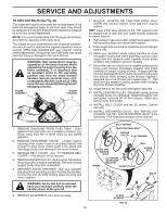
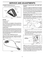
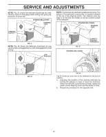
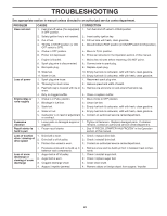
SERVICE AND ADJUSTMENTS TO REMOVE TRACKS (See Fig. 27) • Remove the klik pin and remove track from axle. HOLE KLIK PIN AXLE TRACK TRACK HUB FIG. 27 ENGINE See engine manual. CARBURETOR Your carburetor is not adjustable. Engine performance should not be affected at altitudes up to 7,000 feet (2,134 meters). If your engine does not operate properly due to suspected carburetor problems, take your snow thrower to a qualified service center. ENGINE SPEED Never tamper with the engine governor, which is factory set for proper engine speed. Overspeeding the engine above the factory high speed setting can be dangerous and will void the warranty. If you think the engine-governed high speed needs adjusting, contact a qualified service center, which has proper equipment and experience to make any necessary adjustments. TO ADJUST CABLE TENSION (See Fig. 28) Adjust cable tension by turning the adjuster turn buckle, located on the right hand cable. Grasp the long section tightly and turn the short section to lengthen the adjuster. Adjust until cable is snug. TO ADJUST TRACTION BELT AND AUGER BELT TENSION If the traction or auger belt is slipping because it is not tight enough when engaged, the tension can be increased by adjusting the spring location in the control rod. Unhook the rod from the control lever and move the spring at the bottom of the rod one or two holes closer to the top of the rod. This effectively shortens the rod and increases the belt tension. (See "INSTALL AUGER CONTROL ROD" in the Assembly section of this manual.) INSTRUCTIONS FOR ADJUSTING POWER STEERING CABLES (See Figs. 29-34) Power steering cables can be adjusted to improve performance of steering system. The cable has an in-line adjuster that is turned to shorten or lengthen the cable extension. Location of adjuster is shown in Fig. 29. ADJUSTER FIG. 29 1. Stand the snow thrower on the front of the auger housing. 2. Remove wheels or tracks from axles. To remove tracks it is necessary to remove the cross bar that connects the two track frames together. Remove screws on each end of the cross bar. 3. Remove the plastic power steering covers. Fig. 30. STEERING BELLCRANK ADJUSTER TURN BUCKLE FIG. 28 FIG. 30 NOTE: The position of the steering bellcrank is critical in the operation of the steering system. If it is positioned too high, the steering system will automatically disengage itself while driving, giving the operator the impression of wheel slippage. If the bellcrank is positioned too low, it may be very difficult to disengage the steering clutch while driving, or it may also disengage itself. The correct setting of the bellcrank will give optimum performance. 20
-
 1
1 -
2
-
3
-
4
-
5
-
6
-
7
-
8
-
9
-
10
-
11
-
12
-
13
-
14
-
 15
15 -
 16
16 -
 17
17 -
 18
18 -
 19
19 -
 20
20 -
 21
21 -
 22
22 -
 23
23 -
 24
24 -
 25
25 -
26
-
27
-
28
 |
 |
