Husqvarna 1830EXLT Owners Manual - Page 21
plastic power steering cover and the wheel or track.
 |
View all Husqvarna 1830EXLT manuals
Add to My Manuals
Save this manual to your list of manuals |
Page 21 highlights
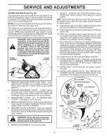
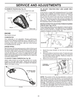
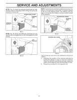
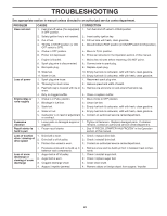
SERVICE AND ADJUSTMENTS NOTE: Fig. 31 shows the bellcrank positioned too high, causing clutch to disengage while driving and giving appearance of wheel slip. STEERING BELLCRANK STEERING YOKE NOTE: Fig 33 shows the bellcrank positioned correctly. The bottom of the bellcrank is horizontal, in a position parallel to the top of the steering clutch. The steering yoke top edge is in line with the middle of the flat vertical surface of the bellcrank. STEERING BELLCRANK STEERING YOKE STEERING CLUTCH HIGH POSITION FIG. 31 NOTE: Fig. 32 shows the bellcrank positioned too low, causing hard disengagement or self-disengagement while driving. LOW POSITION FIG. 33 STEERING BELLCRANK CORRECT POSITION HORIZONTAL FIG. 32 FIG. 34 Fig 34 shows an end view of the bellcrank in the correct position. 4. Adjusting the position of the steering bellcrank by turning the adjuster to raise or lower the bellcrank. When the bellcrank is positioned correctly, replace the plastic power steering cover and the wheel or track. 5. Repeat the procedure for the opposite side. 21
-
 1
1 -
2
-
3
-
4
-
5
-
6
-
7
-
8
-
9
-
10
-
11
-
12
-
13
-
14
-
15
-
 16
16 -
 17
17 -
 18
18 -
 19
19 -
 20
20 -
 21
21 -
 22
22 -
 23
23 -
 24
24 -
 25
25 -
 26
26 -
27
-
28
 |
 |
