Husqvarna 326LS Owners Manual - Page 10
Assembly - trimmer head
 |
View all Husqvarna 326LS manuals
Add to My Manuals
Save this manual to your list of manuals |
Page 10 highlights
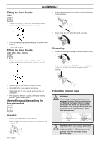
Fitting the loop handle (326C) ASSEMBLY • Push the attachment into the coupling until the attachment snaps into place. • Position the handle on the shaft. Note that the handle must be mounted below the arrow on the shaft. • Before using the unit, tighten the knob securely. • Fit the screw, securing plate and wing nut as shown in the diagram. • Tighten the wing nut. Fitting the loop handle (326L, 326LS, 326Lx, 326LDx) Dismantling: • Loosen the coupling by turning the knob (at least 3 times). • Clip the loop handle onto the shaft. Note that the loop handle must be fitted between the arrows on the shaft. • Push and hold the button (C). While securely holding the engine end, pull the attachment straight out of the coupling. • Slide the spacer into the slot in the loop handle. • 326L/326LS: Fit the nut, washer and screw. 326LX/326LDX: Fit the nut, knob and screw. Do not overtighten. • Now adjust the trimmer to give a comfortable working position. Tighten the bolt/knob. Assembling and dismantling the two-piece shaft (326LDx) Assembly: • Loosen the coupling by turning the knob. • Align the tab of the attachment (A) with the arrow on the coupling (B). B A 10 - English C Fitting the trimmer head WARNING! ! When fitting the cutting attachment it is extremely important that the raised section on the drive disc/support flange engages correctly in the centre hole of the cutting attachment. If the cutting attachment is fitted incorrectly it can result in serious and/or fatal personal injury. WARNING! Never use a cutting attachment ! without an approved guard. See the chapter on Technical data. If an incorrect or faulty guard is fitted this can cause serious personal injury.
-
 1
1 -
2
-
3
-
4
-
 5
5 -
 6
6 -
 7
7 -
 8
8 -
 9
9 -
 10
10 -
 11
11 -
 12
12 -
 13
13 -
 14
14 -
 15
15 -
16
-
17
-
18
-
19
-
20
-
21
-
22
-
23
-
24
-
25
-
26
-
27
-
28
-
29
-
30
-
31
-
32
-
33
-
34
-
35
-
36
-
37
-
38
-
39
-
40
 |
 |
