Husqvarna 535LST Owner Manual - Page 7
To do a check of the stop switch, To do a check of the cutting attachment guard
 |
View all Husqvarna 535LST manuals
Add to My Manuals
Save this manual to your list of manuals |
Page 7 highlights
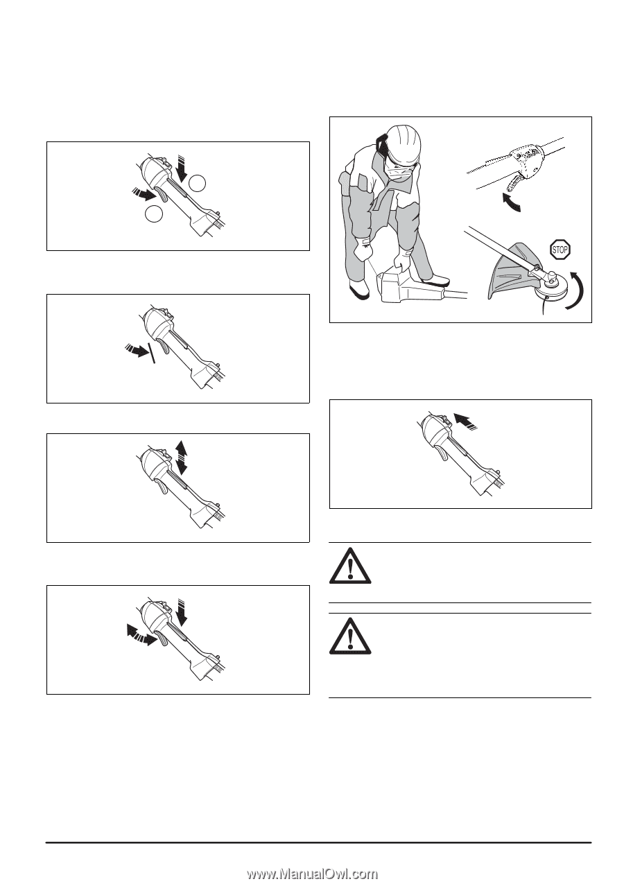
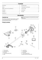
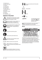
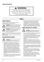
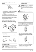
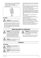
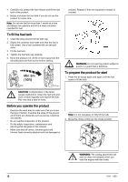
1. Press the throttle trigger lockout (A) and make sure that the throttle control is released (B). When you release the handle the throttle control and the throttle trigger lockout both move back to their initial positions. This movement is controlled by two independent return springs. This arrangement means that the throttle control is automatically locked at the idle setting. 6. Release the throttle and make sure that the cutting attachment stops and remains at a standstill. If the cutting attachment rotates with the throttle in the idle position the carburettor idle setting must be checked. See instructions under the chapter Maintenance on page 14. A B 2. Make sure that the throttle control is locked at the idle setting when the throttle trigger lockout is released. 3. Press the throttle trigger lockout and make sure that it returns to its intial position when you release it. To do a check of the stop switch 1. Start the engine. 2. Move the stop switch to the stop position and make sure that the engine stops. 4. Do a check of the throttle control and throttle trigger lockout move freely and that the return springs work properly. 5. Start the product (refer to the instructions under To prepare the product for start on page 12) and apply full throttle. To do a check of the cutting attachment guard WARNING: Do not use a cutting attachment without an approved and correctly attached cutting attachment guard. Refer to, Accessories on page 19. WARNING: Always use the recommended cutting attachment guard for the cutting attachment that you use. If an incorrect or faulty cutting attachment guard is fitted this can cause serious personal injury. Refer to, Technical data on page 19. The cutting attachment guard prevents injuries from objects that eject in the direction of the operator. It also 1011 - 005 - 7
-
 1
1 -
 2
2 -
 3
3 -
 4
4 -
 5
5 -
 6
6 -
 7
7 -
 8
8 -
 9
9 -
 10
10 -
 11
11 -
 12
12 -
13
-
14
-
15
-
16
-
17
-
18
-
19
-
20
-
21
-
22
-
23
-
24
-
25
-
26
-
27
-
28
-
29
-
30
-
31
-
32
-
33
-
34
-
35
-
36
-
37
-
38
-
39
-
40
-
41
-
42
-
43
-
44
-
45
-
46
-
47
-
48
-
49
-
50
-
51
-
52
-
53
-
54
-
55
-
56
-
57
-
58
-
59
-
60
-
61
-
62
-
63
-
64
-
65
-
66
-
67
-
68
 |
 |