Husqvarna CRT900 Owners Manual - Page 14
Service And Adjustments - 14 inch
 |
View all Husqvarna CRT900 manuals
Add to My Manuals
Save this manual to your list of manuals |
Page 14 highlights
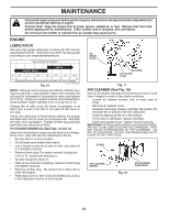
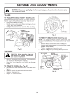
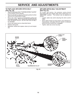
SERVICE AND ADJUSTMENTS CAUTION: Disconnect spark plug wire from spark plug and place wire where it cannot come into contact with plug. TILLER TO ADJUST HANDLE HEIGHT (See Fig. 20) Select handle height best suited for your tilling conditions. Handle height will be different when tiller digs into soil. • First loosen handle lock lever. • Handle can be positioned at different settings between "HIGH" and "LOW" positions. • Retighten handle lock lever securely after adjusting. CLEVIS PIN HANDLE (LOW POSITION) HANDLE (HIGH POSITION) HANDLE LOCK LEVER TIRE CARE Fig. 20 CAUTION: When mounting tires, unless beads are seated, overinflation can cause an explosion. • Maintain 20 pounds of tire pressure. If tire pressures are not equal, tiller will pull to one side. • Keep tires free of gasoline or oil which can damage rubber. TO REMOVE WHEEL (See Fig. 21) • Place blocks under transmission to keep tiller from tipping. • Remove hairpin clip and clevis pin from wheel. • Remove wheel and tire. • Repair tire and reassemble. HAIRPIN CLIP Fig. 21 TO REMOVE BELT GUARD (See Fig. 22) NOTE: For ease of removal, remove hairpin clip and clevis pin from left wheel. Pull wheel out from tiller about 1 inch. • Remove two (2) screws from side of belt guard. • Remove hex nut and washer from bottom of belt guard (located behind wheel). • Pull belt guard out and away from unit. • Replace belt guard by reversing above procedure. BELT GUARD SCREW AND WASHER HEX NUT AND WASHER (LOCATED BEHIND TIRE) SCREW AND WASHER HAIRPIN CLIP AND CLEVIS PIN Fig. 22 14
-
 1
1 -
2
-
3
-
4
-
5
-
6
-
7
-
8
-
 9
9 -
 10
10 -
 11
11 -
 12
12 -
 13
13 -
 14
14 -
 15
15 -
 16
16 -
 17
17 -
 18
18 -
 19
19 -
20
-
21
-
22
-
23
-
24
-
25
-
26
-
27
-
28
-
29
-
30
-
31
-
32
 |
 |
