Husqvarna GT54CS Operation Manual - Page 6
Assembly - transmission
 |
View all Husqvarna GT54CS manuals
Add to My Manuals
Save this manual to your list of manuals |
Page 6 highlights
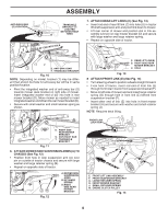
ASSEMBLY BEFORE REMOVING TRACTOR FROM SKID CONNECT BATTERY (See Fig. 1) WARNING: Do not short battery terminals by allowing a wrench or any other object to contact both terminals at the same time. Before connecting battery, remove metal bracelets, wristwatch bands, rings, etc. Positive terminal must be connected first to prevent sparking from accidental grounding. NOTE: If this battery is put into service after month and year indicated on label (label is located between terminals) charge battery for minimum of one hour at 6-10 amps. (See "BATTERY" in the Maintenance section of this manual for charging instructions.) • Determine battery location. Battery location will be under the seat or the hood. • Lift seat pan or hood to raised position. • Remove two terminal caps and discard. • First connect RED battery cable to positive (+) terminal with bolt and nut as shown. Tighten securely. Slide terminal cover over terminal. • Connect BLACK grounding cable to negative (-) terminal with remaining bolt and nut. Tighten securely. • Lower seat pan or hood. NOTE: For battery installation see "REPLACING BATTERY" in the Service and Adjustments section in this manual. TERMINAL COVER NUT LABEL TERMINAL CAP BOLT POSITIVE (RED) CABLE 02605 NEGATIVE (BLACK) CABLE Fig. 1 ADJUST SEAT (See Fig. 2) • Sit in seat. • Lift up adjustment lever (A) and slide seat until a comfortable position is reached which allows you to press clutch/brake pedal all the way down. • Release lever to lock seat in position. NOTE: You may now roll your tractor off the skid. Continue using the instructions that follow to remove the tractor from the skid. WARNING: Before starting, read, understand and follow all instructions in the Operation section of this manual. Ensure tractor is in a well-ventilated area. Ensure the area in front of tractor is clear of other people and objects. TO ROLL TRACTOR OFF SKID (See Operation section for location and function of controls) • Raise attachment lift lever to its highest position. • Release parking brake by depressing brake pedal. • Place freewheel control in "TRANSMISSION DISEN- GAGED" position. (See "TO TRANSPORT" in the Operation section of this manual.) • Roll tractor forward off skid. Continue with the instructions that follow. TO INSTALL MOWER AND DRIVE BELT (See Figs. 3 - 15) 1. SET PARKING BRAKE LEVER AND LOWER ATTACHMENT LIFT LEVER (See Fig. 3 and 4) • Depress clutch/brake pedal all the way down and hold. • Pull parking brake lever up and hold, release pressure from clutch/brake pedal, then release parking brake lever. Pedal should remain in brake position. Ensure parking brake will hold tractor secure. PARKING BRAKE LEVER Fig. 3 CAUTION: Lift lever is spring loaded. Have a tight grip on lift lever, lower it slowly and engage in lowest position. Lift lever is located on left side of fender. A Fig. 2 6
-
 1
1 -
 2
2 -
 3
3 -
 4
4 -
 5
5 -
 6
6 -
 7
7 -
 8
8 -
 9
9 -
 10
10 -
 11
11 -
 12
12 -
13
-
14
-
15
-
16
-
17
-
18
-
19
-
20
-
21
-
22
-
23
-
24
-
25
-
26
-
27
-
28
-
29
-
30
-
31
-
32
-
33
-
34
-
35
-
36
-
37
-
38
-
39
-
40
-
41
-
42
-
43
-
44
-
45
-
46
-
47
-
48
-
49
-
50
-
51
-
52
-
53
-
54
-
55
-
56
-
57
-
58
-
59
-
60
 |
 |