Husqvarna SRD17530 Owners Manual - Page 8
To Assembly Bagger See Figs 6 - 8, To Adjust Hanger Brackets, See Figs. 9 & 10
 |
View all Husqvarna SRD17530 manuals
Add to My Manuals
Save this manual to your list of manuals |
Page 8 highlights
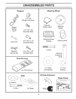
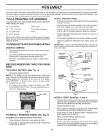
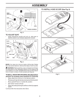
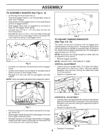
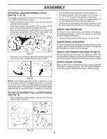
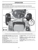
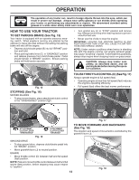
ASSEMBLY TO ASSEMBLY BAGGER (See Figs 6 - 8) • Unfold bag and stand right side up. • Feed front bagger frame (1) up through fabric loops at each side of bagger. • Snap bottom of front bagger frame (1) into snap feature at front of bagger bottom. • Slide bagger fabric loop (2) segments at the ends of bag onto top bagger frame tubing. • Uninstall two (1\4"-20 x 1.15") hex bolts (3) from the front of top frame. • Reinstall the two (1\4"-20 x 1.15") hex bolts (3) through holes at top of the front bagger frame and thread into nuts inside the tubing of top bagger frame. 2 3 1 Fig. 6 • Uninstall (1/4"-20) lock nuts (4) at bottom of front bagger frame. • Unfold cross braces (5) and attach to carriage bolts at bottom corners of front bagger frame. • Reinstall (1/4"-20) lock nuts (4) and tighten until fully seated. NOTE: Verify rear plastic bag shield (6) is snapped in place. 9 7 8 Fig. 8 TO ADJUST HANGER BRACKETS (See Figs. 9 & 10) The tractor comes from the factory with the bagger pivot bracket preset in a fixed position. If necessary, this position can be adjusted to maintain a consistent gap (A) between the fender and the bagger assembly top. An ideal gap is approximately 0.2" (5.1mm). NOTE: As desired, the hanger bracket on either side can be adjusted in this manner. • Remove bagger assembly. NOTE: ADJUST ONLY ONE SIDE AT A TIME. VERTICAL ADJUSTMENT • Loosen nuts on carriage bolts (1) to allow the adjust- ment plate (2) to slide up or down. Move as needed. Retighten nuts securely, locking the adjustment plate in its new position. • Repeat on opposite side. 6 5 4 Fig. 7 • Remove clevis pin (7) and retainer spring (8) from bagger handle (9). • Slide bagger handle (9) down through bagger cover and frame upper weldment holes. • Reinstall clevis pin (7) through hole at bottom of bagger handle and slide retainer spring (8) into hole at the end of the clevis pin until it locks into place. 1 2 Fig. 9 HORIZONTAL ADJUSTMENT • Loosen nuts on carriage bolts (3) to allow the adjustment plate (4) to slide forward or rearwards. Move as needed. Retighten nuts securely, locking the adjustment plate in its new position. • Repeat on opposite side. A 4 3 Fig. 10 • Readjust if necessary. 8
-
 1
1 -
2
-
 3
3 -
 4
4 -
 5
5 -
 6
6 -
 7
7 -
 8
8 -
 9
9 -
 10
10 -
 11
11 -
 12
12 -
 13
13 -
14
-
15
-
16
-
17
-
18
-
19
-
20
-
21
-
22
-
23
-
24
-
25
-
26
-
27
-
28
-
29
-
30
-
31
-
32
-
33
-
34
-
35
-
36
-
37
-
38
-
39
-
40
-
41
-
42
-
43
-
44
-
45
-
46
-
47
-
48
-
49
-
50
-
51
-
52
-
53
-
54
-
55
-
56
-
57
-
58
-
59
-
60
-
61
-
62
-
63
-
64
-
65
-
66
-
67
-
68
 |
 |
