Husqvarna W448 Operation Manual - Page 16
Cutting Height Adjustment
 |
View all Husqvarna W448 manuals
Add to My Manuals
Save this manual to your list of manuals |
Page 16 highlights
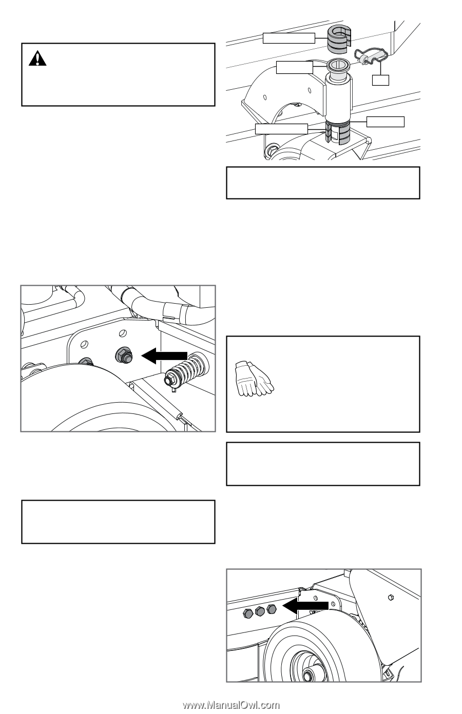
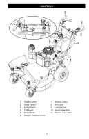
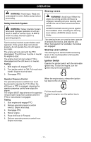
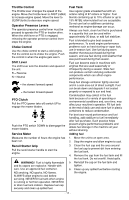
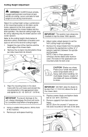
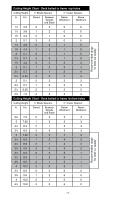
Cutting Height Adjustment ½" Spacers WARNING! ALWAYS block wheels, engage parking brake and know all jack stands are strong, secure and able to hold weight of unit during maintenance. Bushing Pin Adjust the cutting height using a combination of the mounting location on the deck carrier frame, spacers on the front casters and spacers between the mower blades and the deck spindles. The desired cutting height may be set by adjusting only the blade spacers and caster spacers. Refer to the cutting height charts below to determine which combination of location and spacers will set the desired cutting height. 1. Support the rear of the machine and the back edge of the mower deck. 2. Remove the six deck mounting bolts (three per side, lower bolt not shown). ½" Spacers Washer IMPORTANT The washer must always be installed on top the lower HOC spacers. 6. Adjust caster wheel spacers to set the front cutting height accordingly. 7. Remove the mower blade from the spindle and place the appropriate number of ¼" spacers (washers) between the spindle and the blade. NOTE: If two or three spacers are removed, shorter blade bolts must be used. The bolts for this application are mounted under the belt cover. CAUTION! Blades are sharp. Protect your hands with gloves and/or wrap blades with a heavy cloth when handling. On multi-blade mowers, rotation of one blade will cause all blades to rotate. 3. Align the mounting holes in the deck frame with the unit frame and reinstall the mounting bolts in the appropriate holes and tighten to 35 -40 lbf-ft (47- 54 N•m). IMPORTANT To prevent damage to the unit, always disengage the drive and come to a complete stop before changing gears. 4. Using a suitable lifting device, lift the front of the machine. 5. Remove pin and spacer bushing. IMPORTANT DO NOT allow the blade to be less than 1/8" (3.2 mm) above the lip of the mower deck. 8. Replace mower blade and tighten blade bolt to 120 lbf-ft (163 N•m). 9. Remove supports from deck and mower frame. NOTE: Store the unused ¼" spacers on hex bolts mounted on the rear of the deck. - 16 -
-
 1
1 -
2
-
3
-
4
-
5
-
6
-
7
-
8
-
9
-
10
-
 11
11 -
 12
12 -
 13
13 -
 14
14 -
 15
15 -
 16
16 -
 17
17 -
 18
18 -
 19
19 -
 20
20 -
 21
21 -
22
-
23
-
24
-
25
-
26
-
27
-
28
-
29
-
30
-
31
-
32
 |
 |