Husqvarna YT42CS Operation Manual - Page 20
ATTACH REAR LIFT LINKS C - Lift rear corner
 |
View all Husqvarna YT42CS manuals
Add to My Manuals
Save this manual to your list of manuals |
Page 20 highlights
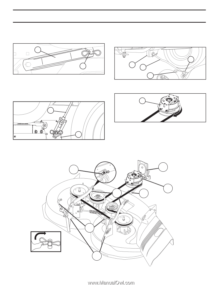
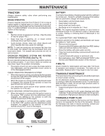
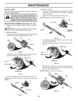
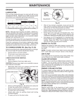
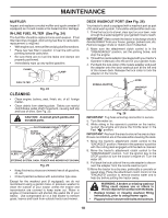
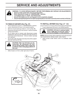
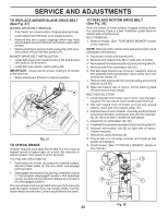
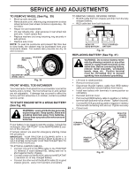
SERVICE AND ADJUSTMENTS • ATTACH MOWER SIDE SUSPENSION ARMS (A) TO CHASSIS - Position hole in arm over pin (B) on outside of tractor chassis and secure with retainer spring. • Repeat on opposite side of tractor. A • ATTACH FRONT LINK (E) - Work from left side of tractor. Insert rod end of link assembly through front hole in tractor front suspension bracket (F). • Insert end of link (E) into hole in front mower bracket (H) and secure with washer and retainer spring (J). B Fig. 28 • ATTACH REAR LIFT LINKS (C) - Lift rear corner of mower and position slot in link assembly over pin on rear mower bracket (D) and secure with washer and retainer spring. J F E H Fig. 30 • Install belt onto electric clutch pulley (M). M C D Fig. 29 Fig. 31 IMPORTANT: CHECK BELT FOR PROPER ROUTING IN ALL MOWER PULLEY GROOVES. • Raise attachment lift lever to highest position. • If necessary, adjust gauge wheels before operating mower as shown in the Operation section of this manual. B F M A E C D Fig. 32 20
-
 1
1 -
2
-
3
-
4
-
5
-
6
-
7
-
8
-
9
-
10
-
11
-
12
-
13
-
14
-
 15
15 -
 16
16 -
 17
17 -
 18
18 -
 19
19 -
 20
20 -
 21
21 -
 22
22 -
 23
23 -
 24
24 -
 25
25 -
26
-
27
-
28
-
29
-
30
-
31
-
32
-
33
-
34
-
35
-
36
-
37
-
38
-
39
-
40
-
41
-
42
-
43
-
44
-
45
-
46
-
47
-
48
-
49
-
50
-
51
-
52
-
53
-
54
-
55
-
56
 |
 |