Husqvarna YT42XLS Owners Manual - Page 24
To Remove Wheel See Fig. 40, Front Wheel Toe-in/camber, To Replace Motion Drive Belt, See Fig. 39
 |
View all Husqvarna YT42XLS manuals
Add to My Manuals
Save this manual to your list of manuals |
Page 24 highlights
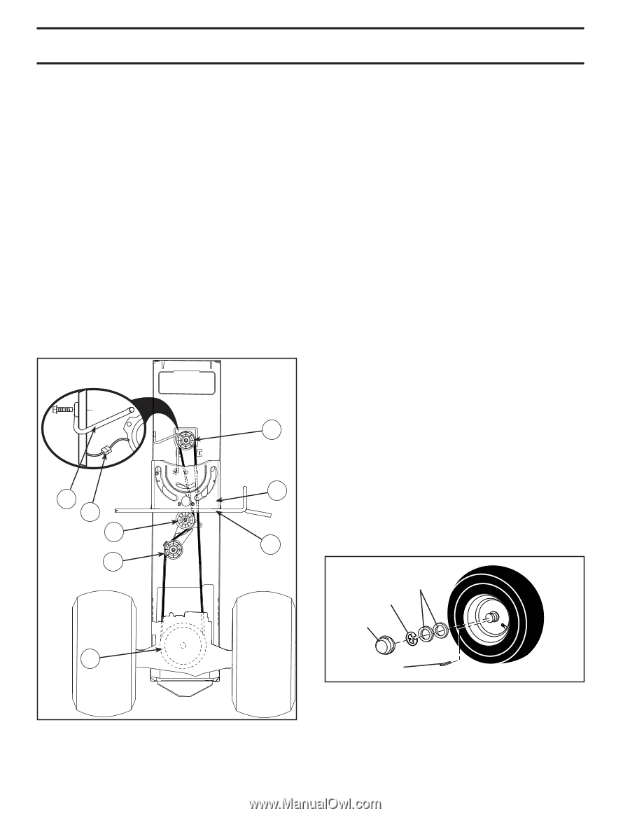
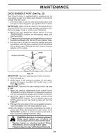
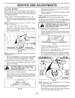
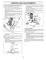
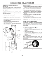
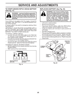
SERVICE AND ADJUSTMENTS TO REPLACE MOTION DRIVE BELT (See Fig. 39) Park the tractor on level surface. Engage parking brake. For assistance, there is a belt installation guide decal on bottom side of left footrest. BELT REMOVAL 1. Remove mower (See "TO REMOVE MOWER" section in this manual). NOTE: Observe entire motion drive belt and position of all belt guides and keepers. 2. Disconnect clutch wire harness (A). 3. Remove anti-rotation link (B) on right side of tractor. 4. Remove belt from stationary idler (C) and clutching idler (D). 5. Pull belt slack toward rear of tractor. Carefully remove belt upwards from transmission input pulley and over cooling fan blades (F). 6. Remove belt downward from engine pulley and around electric clutch (G). 7. Slide belt toward rear of tractor, off the steering plate (H) and remove from tractor. G H B A C J D BELT INSTALLATION - 1. Install new belt from tractor rear to front, over the steering plate (H) and above clutch brake pedal shaft (J). 2. Pull belt toward front of tractor and roll belt around electric clutch and onto engine pulley (G). 3. Pull belt toward rear of tractor. Carefully work belt down around transmission cooling fan and onto the input pulley (F). Be sure belt is inside the belt keeper. 4. Install belt through stationary idler (C) and clutching idler (D). 5. Reinstall anti-rotation link (B) on right side of tractor. Tighten securely. 6. Reconnect clutch harness (A). 7. Make sure belt is in all pulley grooves and inside all belt guides and keepers. 8. Install mower (See "TO INSTALL MOWER" section in this manual). FRONT WHEEL TOE-IN/CAMBER Your new tractor front wheel toe-in and camber is set at the factory and is normal. The front wheel toe-in and camber are not adjustable. If damage has occurred to affect the factory set front wheel toe-in or camber, contact a qualified service center. TO REMOVE WHEEL (See Fig. 40) • Block up axle securely. • Remove axle cover, retaining ring and washers to allow wheel removal (rear wheel contains a square key - Do not lose). • Repair tire and reassemble. • On rear wheels only: align grooves in rear wheel hub and axle. Insert square key. • Replace washers and snap retaining ring securely in axle groove. • Replace axle cover. NOTE: To seal tire punctures and prevent flat tires due to slow leaks, tire sealant may be purchased from your local parts dealer. Tire sealant also prevents tire dry rot and corrosion. WASHERS RETAINING RING AXLE COVER F SQUARE KEY (REAR WHEEL ONLY) Fig. 40 Fig. 39 24
-
 1
1 -
2
-
3
-
4
-
5
-
6
-
7
-
8
-
9
-
10
-
11
-
12
-
13
-
14
-
15
-
16
-
17
-
18
-
 19
19 -
 20
20 -
 21
21 -
 22
22 -
 23
23 -
 24
24 -
 25
25 -
 26
26 -
 27
27 -
 28
28 -
 29
29 -
30
-
31
-
32
-
33
-
34
-
35
-
36
-
37
-
38
-
39
-
40
-
41
-
42
-
43
-
44
-
45
-
46
-
47
-
48
-
49
-
50
-
51
-
52
-
53
-
54
-
55
-
56
-
57
-
58
-
59
-
60
-
61
-
62
-
63
-
64
-
65
-
66
-
67
-
68
 |
 |