Husqvarna YT42XLS Owners Manual - Page 5
Unassembled Parts, Assembly - transmission
 |
View all Husqvarna YT42XLS manuals
Add to My Manuals
Save this manual to your list of manuals |
Page 5 highlights
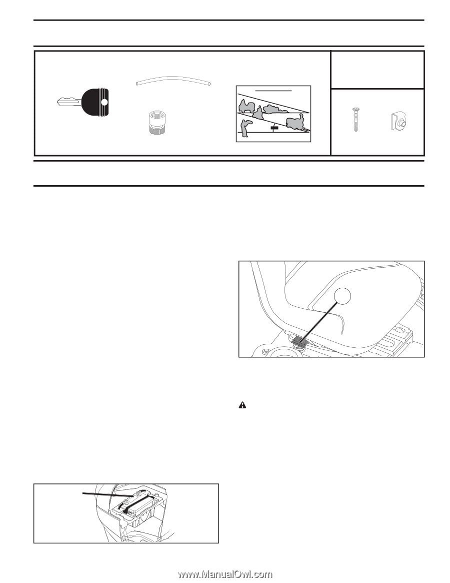
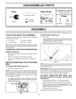
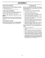
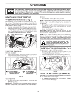
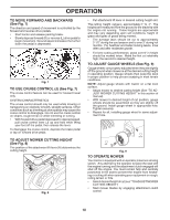
UNASSEMBLED PARTS Keys Key(s) (1) Oil Drain Tube (1) Quick Connect Slope Sheet *Installed by Dealer *Brush Guard Kit *Pedal (2) Screw (2) Nut U -Channel ASSEMBLY Your new tractor has been assembled at the factory with the exception of those parts left unassembled for shipping purposes. TOOLS REQUIRED FOR ASSEMBLY A socket wrench set will make assembly easier. Standard wrench sizes are listed. (1) 1/2" wrench Tire pressure gauge (2) 7/16" wrenches Utility knife Pliers When right or left hand is mentioned in this manual, it means when you are in the operating position (seated behind the steering wheel). TO REMOVE TRACTOR FROM CARTON UNPACK CARTON • Remove all accessible loose parts and parts cartons from carton. • Remove end panels and lay side panels flat. • Check for any additional loose parts or cartons and remove. BEFORE REMOVING TRACTOR FROM SKID TO CHECK BATTERY (See Fig. 1) • Lift hood to raised position. NOTE: If this battery is put into service after month and year indicated on label (label is located between terminals) charge battery for minimum of one hour at 6-10 amps. (See "BATTERY" in Maintenance section of this manual for charging instructions). • For battery and battery cable installation see "REPLACING BATTERY" in the "Service and Adjustments" section in this manual. LABEL ADJUST SEAT (See Fig. 2) • Sit in seat. • Lift up adjustment lever (A) and slide seat until a com- fortable position is reached which allows you to press clutch/brake pedal all the way down. • Release lever to lock seat in position. A Fig. 2 NOTE: You may now roll your tractor off the skid. Follow the appropriate instruction on the next page to remove the tractor from the skid. WARNING: Before starting, read, understand and follow all instructions in the Operation section of this manual. Be sure tractor is in a well-ventilated area. Be sure the area in front of tractor is clear of other people and objects. TO ROLL TRACTOR OFF SKID (See Operation section for location and function of controls) • Raise attachment lift lever to its highest position. • Release parking brake by depressing brake pedal. • Place freewheel control in disengaged position to dis- engage transmission (See "TO TRANSPORT" in the Operation section of this manual). • Roll tractor forward off skid. Continue with the instructions that follow. Fig. 1 5
-
 1
1 -
 2
2 -
 3
3 -
 4
4 -
 5
5 -
 6
6 -
 7
7 -
 8
8 -
 9
9 -
 10
10 -
 11
11 -
12
-
13
-
14
-
15
-
16
-
17
-
18
-
19
-
20
-
21
-
22
-
23
-
24
-
25
-
26
-
27
-
28
-
29
-
30
-
31
-
32
-
33
-
34
-
35
-
36
-
37
-
38
-
39
-
40
-
41
-
42
-
43
-
44
-
45
-
46
-
47
-
48
-
49
-
50
-
51
-
52
-
53
-
54
-
55
-
56
-
57
-
58
-
59
-
60
-
61
-
62
-
63
-
64
-
65
-
66
-
67
-
68
 |
 |