IBM 03R5900 Service Guide - Page 18
connectors, models
 |
View all IBM 03R5900 manuals
Add to My Manuals
Save this manual to your list of manuals |
Page 18 highlights
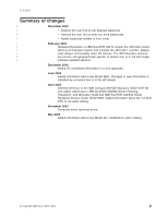
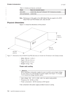
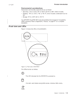
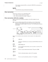
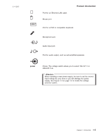
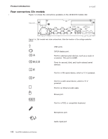
Product introduction | | 11-9-2005 This network connection LED is on when the 4810/4910 is connected to a hub or switch. This LED blinks during receive/send transmission. Rear connectors | See the rear connector for your 4810/4910 model: | v Go to "Rear connectors 4810 (31x models)." | v Go to "Rear connectors 32x models" on page 1-6. | Rear connectors 4810 (31x models) | Figure 1-3 shows the connections available on the 4810 (models 31x) and | 4910-32H: Note: Not sure whether placing 4910 in the heading is correct. Please advise whether the 4910 models would follow the current grouping of the rear connectors for the 4810 models 31x and 32x. If not, how should the 4910 be incorporated? voltage switch C A B D Ethernet Figure 1-3. 31x models rear view connections. Note the location of the voltage selection switch. A B C D 1-4 SurePOS Installation and Service USB ports. Parallel port. Optionally, you can plug a parallel-interface device into this port. SVGA display port. Port for external serial devices, such as a scale or a scanner. This port is COM1. Port for a second external serial device. This port is COM2. Port for a third serial device, which is 12 V powered. Port for a fourth serial device, which is 12 V powered.
-
 1
1 -
2
-
3
-
4
-
5
-
6
-
7
-
8
-
9
-
10
-
11
-
12
-
 13
13 -
 14
14 -
 15
15 -
 16
16 -
 17
17 -
 18
18 -
 19
19 -
 20
20 -
 21
21 -
 22
22 -
 23
23 -
24
-
25
-
26
-
27
-
28
-
29
-
30
-
31
-
32
-
33
-
34
-
35
-
36
-
37
-
38
-
39
-
40
-
41
-
42
-
43
-
44
-
45
-
46
-
47
-
48
-
49
-
50
-
51
-
52
-
53
-
54
-
55
-
56
-
57
-
58
-
59
-
60
-
61
-
62
-
63
-
64
-
65
-
66
-
67
-
68
 |
 |