IBM 17351LX User Guide - Page 16
Models and Features, IBM Conversion Options and Console Switch Cables, daisy-chaining - kvm
 |
View all IBM 17351LX manuals
Add to My Manuals
Save this manual to your list of manuals |
Page 16 highlights
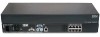
2 IBM Rack Console Switch Installation and User's Guide Models and Features An IBM 1 x 8 Rack Console Switch supports access by a single local user. An IBM 2 x 16 Rack Console Switch supports simultaneous access by two local users. The following table summarizes the features provided by the two types of switches. Table 1.1: Rack console switch models, ports, users, maximum tiered and daisy-chained servers Model ARI Ports Local Users Maximum Servers Connected to Tiered Switches or Daisy-chained 1x8 8 1 (A) 128 2 x 16 16 2 (A and B) 256 IBM Conversion Options and Console Switch Cables COs are first connected to the servers and then are connected to ARI ports on the rack console switch by means of separate CAT 5 cables. Firmware on the COs may also be upgraded. Each console switch cable has a built-in 3 meter (10 foot) CAT 5 cable for connecting a server to an ARI port. Firmware on the console switch cables is not upgradable. The KVM (KCO) and USB (UCO) conversion options each have two ARI jacks on the back. For daisy-chaining, one ARI jack can be connected to an ARI port on the rack console switch, and the other jack can be connected either to another CO of the same type (KCO or UCO) or to a terminator plug. Up to 16 KCO or UCO conversion options can be connected to a single rack console switch port to daisy-chain up to 16 servers per port. Either a PS/2 console switch cable or a KCO can be used to connect a server that has PS/2-based KVM ports. PS/2 console switch cable KCO Figure 1.1: Options for connecting servers that have PS2-based KVM ports
-
 1
1 -
2
-
3
-
4
-
5
-
6
-
7
-
8
-
9
-
10
-
 11
11 -
 12
12 -
 13
13 -
 14
14 -
 15
15 -
 16
16 -
 17
17 -
 18
18 -
 19
19 -
 20
20 -
 21
21 -
22
-
23
-
24
-
25
-
26
-
27
-
28
-
29
-
30
-
31
-
32
-
33
-
34
-
35
-
36
-
37
-
38
-
39
-
40
-
41
-
42
-
43
-
44
-
45
-
46
-
47
-
48
-
49
-
50
-
51
-
52
-
53
-
54
-
55
-
56
-
57
-
58
-
59
-
60
-
61
-
62
-
63
-
64
-
65
-
66
-
67
-
68
-
69
-
70
-
71
-
72
-
73
-
74
-
75
-
76
-
77
-
78
-
79
-
80
-
81
-
82
-
83
-
84
-
85
-
86
-
87
-
88
-
89
-
90
-
91
-
92
-
93
-
94
 |
 |
