IBM 206m User Guide - Page 51
Installing, adapter
 |
UPC - 000435840578
View all IBM 206m manuals
Add to My Manuals
Save this manual to your list of manuals |
Page 51 highlights
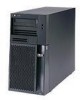
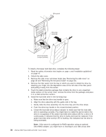
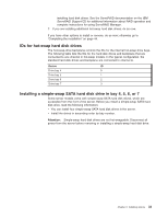
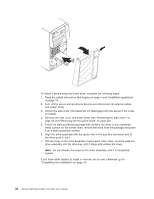
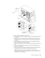
The black connector is attached to the master IDE device. The gray middle connector is attached to the subordinate IDE device. - (Optional) Diskette drive: The narrower signal cable has two connectors. One is attached to the diskette drive, and the other is attached to the connector (FDD1) on the system board. - SATA: The narrower, black signal cable has two connectors. One is connected to the non-hot-swap SATA drive, and the other is attached to the connector on the system board. Simple-swap SATA models come with four SATA cables that are already connected to the system board and the back panel at the rear of the simple-swap drives. Hot-swap SATA models come with a single data cable that connects the SAS/SATA controller to the hot-swap backplane. This cable provides inherent connectivity for the four SATA drives that the server supports. Therefore, additional cabling is not required for these drives. - SAS: Hot-swap SAS models come with a single data cable that connects the SAS/SATA controller to the hot-swap backplane. This cable provides inherent connectivity for the four SAS drives that the server supports. Therefore, additional cabling is not required for these drives. For more information about the requirements for SAS cable and connecting SAS devices, see the documentation that comes with these devices. For a list of supported options for the server, see http://www.ibm.com/servers/ eserver/serverproven/compat/us/. Installing an adapter The following notes describe the types of adapters that the server supports and other information that you must consider when installing an adapter. v Locate the documentation that comes with the adapter and follow those instructions in addition to the instructions in this section. If you need to change the switch setting or jumper settings on the adapter, follow the instructions that come with the adapter. v Read the documentation that comes with your operating system. v The server comes with two PCI slots and two PCI Express slots on the main system board. If your model comes with the optional PCI-X expansion card, it provides two PCI-X slots. v You can install full-length adapters that are included in the ServerProven® list in slots 1 through 6 (depending on your model). v The 32-bit slots 3 and 4 support 5.0 V keyed PCI adapters; they do not support 3.3 V keyed adapters. Universal adapters are supported in slots 3 and 4 if they are universally keyed and the server is not a hot-swap model. If you are installing 64-bit adapters in a hot-swap model, you must install them only in slots 5 and 6. v An optional IBM Remote Supervisor Adapter II can be installed only in the following slots: PCI slots 3 and 4. Use the ribbon cable that comes with this adapter to connect it to the Remote Supervisor Adapter II cable connector on the system board. For additional information, see the documentation that comes with this adapter. v When you start the server for the first time after installing a Remote Supervisor Adapter II, the startup process will take several minutes longer than a typical startup. Chapter 2. Installing options 37
-
 1
1 -
2
-
3
-
4
-
5
-
6
-
7
-
8
-
9
-
10
-
11
-
12
-
13
-
14
-
15
-
16
-
17
-
18
-
19
-
20
-
21
-
22
-
23
-
24
-
25
-
26
-
27
-
28
-
29
-
30
-
31
-
32
-
33
-
34
-
35
-
36
-
37
-
38
-
39
-
40
-
41
-
42
-
43
-
44
-
45
-
 46
46 -
 47
47 -
 48
48 -
 49
49 -
 50
50 -
 51
51 -
 52
52 -
 53
53 -
 54
54 -
 55
55 -
 56
56 -
57
-
58
-
59
-
60
-
61
-
62
-
63
-
64
-
65
-
66
-
67
-
68
-
69
-
70
-
71
-
72
-
73
-
74
-
75
-
76
-
77
-
78
-
79
-
80
-
81
-
82
-
83
-
84
-
85
-
86
-
87
-
88
-
89
-
90
-
91
-
92
 |
 |