IBM 3110X User Guide - Page 16
Connectors and LEDs - cisco catalyst switch
 |
UPC - 000435956712
View all IBM 3110X manuals
Add to My Manuals
Save this manual to your list of manuals |
Page 16 highlights
Connectors and LEDs Figure 6 shows the front panels of the Cisco Catalyst Switch Module 3110G and 3110X. Figure 6. Front panel of the Cisco Catalyst Switch Module 3110G (left) and 3110X (right). The front panel contains the components identified in Table 9. Table 9. Front panel callouts Callout Description 1, 8 Stack member LED 2, 9 Mode button 3, 10 Fault/stack mode LED 4, 11 System power LED 5, 12 Stack master LED 6, 7 Port link and activity LEDs for each RJ-45 (3110G) 13 X2 port status LEDs (3110X) Cisco Catalyst Switch Modules 3110G and 3110X for IBM BladeCenter 16
-
 1
1 -
2
-
3
-
4
-
5
-
6
-
7
-
8
-
9
-
10
-
 11
11 -
 12
12 -
 13
13 -
 14
14 -
 15
15 -
 16
16 -
 17
17 -
 18
18 -
 19
19 -
 20
20
 |
 |

Cisco Catalyst Switch Modules 3110G and 3110X for IBM BladeCenter
16
Connectors and LEDs
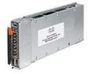
Figure 6 shows the front panels of the Cisco Catalyst Switch Module 3110G and 3110X.
Figure 6. Front panel of the Cisco Catalyst Switch Module 3110G (left) and 3110X (right).
The front panel contains the components identified in Table 9.
Table 9. Front panel callouts
Callout
Description
1, 8
Stack member LED
2, 9
Mode button
3, 10
Fault/stack mode LED
4, 11
System power LED
5, 12
Stack master LED
6, 7
Port link and activity LEDs
for each RJ-45 (3110G)
13
X2 port status LEDs (3110X)