IBM 326m Hardware Maintenance Manual - Page 49
Installing, drive
 |
UPC - 000435835093
View all IBM 326m manuals
Add to My Manuals
Save this manual to your list of manuals |
Page 49 highlights
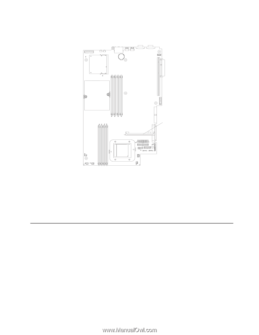
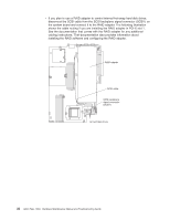
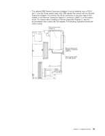
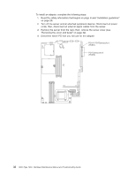
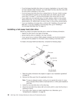
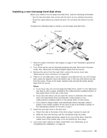
13. If you installed a full-length adapter in PCI-X slot 1, secure the adapter by flexing the adapter-retention bracket toward the front of the server and inserting the front corners of the adapter into the recesses in the latch. Adapter-retention bracket 14. Perform any configuration tasks required for the adapter. If you installed a Remote Supervisor Adapter II, see the documentation that comes with the Remote Supervisor Adapter II for information about installing the Remote Supervisor Adapter II firmware and configuring the adapter. After you initially configure the adapter, create a backup copy of the configuration so that if you need to replace the adapter in the future, you can restore the configuration and resume normal operation more quickly. 15. If you have other options to install, install them now. Otherwise, go to "Completing the installation" on page 53. Installing a hard disk drive The following notes describe the types of hard disk drives that your server supports and other information that you must consider when installing a hard disk drive: v The server supports two 25.4-mm (1-inch), slim, 3.5-inch hard disk drives. SCSI server models come with a hot-swap SCSI backplane. v The SCSI server models support low voltage differential (LVD) hot-swap drives. Each hot-swap drive is in a tray, which has a green activity LED and an amber status LED in the upper-right corner. These LEDs are lit if the drive is active and, in some cases, if the drive fails. Each hot-swap drive has a single-connectorattached (SCA) connector, which is connected directly into the hot-swap SCSI backplane. The backplane is attached to connector J12 on the system board and controls the SCSI IDs for the hot-swap drives. Note: The drive in bay 1 is assigned SCSI ID 0; the drive in bay 2 is assigned SCSI ID 1. Chapter 4. Installing options 39
-
 1
1 -
2
-
3
-
4
-
5
-
6
-
7
-
8
-
9
-
10
-
11
-
12
-
13
-
14
-
15
-
16
-
17
-
18
-
19
-
20
-
21
-
22
-
23
-
24
-
25
-
26
-
27
-
28
-
29
-
30
-
31
-
32
-
33
-
34
-
35
-
36
-
37
-
38
-
39
-
40
-
41
-
42
-
43
-
 44
44 -
 45
45 -
 46
46 -
 47
47 -
 48
48 -
 49
49 -
 50
50 -
 51
51 -
 52
52 -
 53
53 -
 54
54 -
55
-
56
-
57
-
58
-
59
-
60
-
61
-
62
-
63
-
64
-
65
-
66
-
67
-
68
-
69
-
70
-
71
-
72
-
73
-
74
-
75
-
76
-
77
-
78
-
79
-
80
-
81
-
82
-
83
-
84
-
85
-
86
-
87
-
88
-
89
-
90
-
91
-
92
-
93
-
94
-
95
-
96
-
97
-
98
-
99
-
100
-
101
-
102
-
103
-
104
-
105
-
106
-
107
-
108
-
109
-
110
-
111
-
112
-
113
-
114
-
115
-
116
-
117
-
118
-
119
-
120
-
121
-
122
-
123
-
124
-
125
-
126
-
127
-
128
-
129
-
130
-
131
-
132
-
133
-
134
-
135
-
136
-
137
-
138
-
139
-
140
-
141
-
142
-
143
-
144
-
145
-
146
-
147
-
148
-
149
-
150
-
151
-
152
-
153
-
154
-
155
-
156
-
157
-
158
-
159
-
160
-
161
-
162
-
163
-
164
-
165
-
166
-
167
-
168
-
169
-
170
-
171
-
172
 |
 |