IBM 32R1860 User Guide - Page 11
Connectors and LEDs, Network cabling requirements
 |
UPC - 000435853387
View all IBM 32R1860 manuals
Add to My Manuals
Save this manual to your list of manuals |
Page 11 highlights
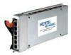
Connectors and LEDs Figure 5 shows the front panel of the BNT Layer 2/3 Copper and Fiber Gigabit Ethernet Switch Modules. Figure 5. Front panel of the BNT Layer 2/3 Copper (left) and Fiber (right) Gigabit Ethernet Switch Modules The front panel contain the following components: z LEDs display the status of the switch module and the network: OK (indicating that the switch module has passed the power-on self-test (POST) with no critical faults and is operational) and switch module error (indicating that the switch module has failed the POST or detected an operational fault). z One USB RS-232 console port provides an additional means to install software and configure the switch module. This USB-style connector enables connection of a special serial cable that is supplied with the switch module. z The copper model of the switch module has six external 1000BASE-T Ethernet ports for 10/100/1000 Mbps connections to external Ethernet devices. z The fiber model of the switch module has six external 1000BASE SX SFP transceiver ports for 1000 Mbps connections to external Ethernet devices. z Each external port on the switch module contains an Ethernet link OK LED and an Ethernet Tx/Rx LED. Network cabling requirements The following network cable is required for the fiber switch module: z 1000BASE-SX: 850 Nm wavelength, multimode fiber, 50 µ or 62.5 µ (550 meters maximum), with LC duplex connector Note: Fiber connections use SFP transceivers that provide 1000BASE-SX (850 nm wavelength) BNT Layer 2/3 Copper and Fiber Gigabit Ethernet Switch Modules for IBM BladeCenter 11
-
 1
1 -
2
-
3
-
4
-
5
-
 6
6 -
 7
7 -
 8
8 -
 9
9 -
 10
10 -
 11
11 -
 12
12 -
 13
13 -
 14
14
 |
 |
