IBM 88728AU Installation Guide
IBM 88728AU - System x3950 - 8872 Datacenter High Availability Manual
 |
UPC - 000435957627
View all IBM 88728AU manuals
Add to My Manuals
Save this manual to your list of manuals |
IBM 88728AU manual content summary:
- IBM 88728AU | Installation Guide - Page 1
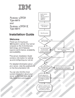
System x3950 Type 8872 and System x3950 E Type 8874 Installation Guide Welcome. Thank you for buying an IBM System x server. Your server is based on the X-Architecture technology, and it features superior performance, availability, and scalability. This server Installation Guide contains information - IBM 88728AU | Installation Guide - Page 2
See the troubleshooting information that comes with the server to determine the cause of the problem and the action to take. Register the server. Go to http://www.ibm.com/support/mysupport/ View information about IBM Support Line at http://www.ibm.com/services/sl/products/ or view support telephone - IBM 88728AU | Installation Guide - Page 3
IBM System x3950 Type 8872 and System x3950 E Type 8874 Installation Guide - IBM 88728AU | Installation Guide - Page 4
read the general information in "Notices" on page 83, and the Warranty and Support Information document on the IBM Documentation CD. Fourth Edition (April 2006) © Copyright International Business Machines Corporation 2006. All rights reserved. US Government Users Restricted Rights - Use, duplication - IBM 88728AU | Installation Guide - Page 5
a memory card 14 Installing an additional microprocessor 15 Installing an adapter 19 Completing the installation 21 Connecting the cables 21 Updating the server configuration 22 SMP Expansion cabling 23 Chapter 3. Server controls, connectors, LEDs, and power 31 Front view 31 Rear view 33 - IBM 88728AU | Installation Guide - Page 6
conformance statement 87 Taiwanese Class A warning statement 88 Chinese Class A warning statement 88 Japanese Voluntary Control Council for Interference (VCCI) statement . . . 88 Index 89 iv IBM System x3950 Type 8872 and System x3950 E Type 8874: Installation Guide - IBM 88728AU | Installation Guide - Page 7
, leggere le Informazioni sulla Sicurezza. Les sikkerhetsinformasjonen (Safety Information) før du installerer dette produktet. Antes de instalar este produto, leia as Informações sobre Segurança. © Copyright IBM Corp. 2006 v - IBM 88728AU | Installation Guide - Page 8
sure to read all caution and danger statements in this documentation before performing the instructions. Read any additional safety information that comes with the server or optional device before you install the device. vi IBM System x3950 Type 8872 and System x3950 E Type 8874: Installation Guide - IBM 88728AU | Installation Guide - Page 9
is evidence of fire, water, or structural damage. v Disconnect the attached power cords, telecommunications systems, networks, and modems before you open the device covers, unless instructed otherwise in the installation and configuration procedures. v Connect and disconnect cables as described in - IBM 88728AU | Installation Guide - Page 10
could result in exposure to hazardous laser radiation. There are no serviceable parts inside the device. v Use of controls or adjustments view directly with optical instruments, and avoid direct exposure to the beam. viii IBM System x3950 Type 8872 and System x3950 E Type 8874: Installation Guide - IBM 88728AU | Installation Guide - Page 11
Statement 4: ≥ 18 kg (39.7 lb) ≥ 32 kg (70.5 lb) CAUTION: Use safe practices when lifting. Statement 5: ≥ 55 kg (121.2 lb) CAUTION: The power control button on the device and the power switch on the power supply do not turn off the electrical current supplied to the device. The device also - IBM 88728AU | Installation Guide - Page 12
. There are no serviceable parts inside these components. If you suspect a problem with one of these parts, contact a service technician. Statement 10: CAUTION: Do not place any object on top of rack-mounted devices. x IBM System x3950 Type 8872 and System x3950 E Type 8874: Installation Guide - IBM 88728AU | Installation Guide - Page 13
Guide contains instructions for setting up your IBM® System x3950 Type 8872 or System x3950 E Type 8874 server and basic instructions for installing some options. More detailed instructions for installing options are in the User's Guide on the IBM Documentation CD, which comes with the server - IBM 88728AU | Installation Guide - Page 14
in this document show the System x3950 server, unless otherwise noted. ID labels For a list of supported options for the server, go to the ServerProven® Web site at http://www.ibm.com/servers/eserver/serverproven/compat/us/. See the Rack Installation Instructions document for complete rack - IBM 88728AU | Installation Guide - Page 15
operating system, server from the Product menu. The Available Topics list displays all the documents for the server View Book to view IBM problem situations. v Attention: These notices indicate potential damage to programs, devices, or data. An attention notice is placed just before the instruction - IBM 88728AU | Installation Guide - Page 16
information is a summary of the features and specifications of the server. Depending on the server model, some features might not be available, or some specifications below which a large number of computers will operate. 4 IBM System x3950 Type 8872 and System x3950 E Type 8874: Installation Guide - IBM 88728AU | Installation Guide - Page 17
server watts) per hour v Broadcom 5704C dual 10/100/1000 Gigabit Ethernet controllers v ATI 7000-M video - 16 MB video memory - SVGA compatible v Mouse connector v Keyboard connector v Serial connector v SMP Expansion Ports support: Upgradeable microcode: System BIOS, diagnostics, service - IBM 88728AU | Installation Guide - Page 18
server and operating system support hot-swap capability, you can remove or install the component while the server is running. (Orange can also indicate touch points on hot-swap components.) See the instructions tray Bezel 6 IBM System x3950 Type 8872 and System x3950 E Type 8874: Installation Guide - IBM 88728AU | Installation Guide - Page 19
be hot-swapped, which means that if the server and operating system support hot-swap capability, you can remove or install the component while the server is running. (Orange can also indicate touch points on hot-swap components.) See the instructions for removing or installing a specific hot-swap - IBM 88728AU | Installation Guide - Page 20
avoid this potential problem, always use an electrostatic-discharge wrist strap or other grounding system when working inside the server with the power on. The server supports hot-swap devices to build up around you. 8 IBM System x3950 Type 8872 and System x3950 E Type 8874: Installation Guide - IBM 88728AU | Installation Guide - Page 21
example, wear an electrostatic-discharge wrist strap, if one is available. Always use an electrostatic-discharge wrist strap or other grounding system when working inside the server with the power on. v Handle the device carefully, holding it by its edges or its frame. v Do not touch solder joints - IBM 88728AU | Installation Guide - Page 22
disk arrays before installing the operating system. See the ServeRAID™ documentation on the IBM ServeRAID Support CD for additional information about RAID operation and complete instructions for using ServeRAID Manager. 10 IBM System x3950 Type 8872 and System x3950 E Type 8874: Installation Guide - IBM 88728AU | Installation Guide - Page 23
information that you must consider when installing DIMMs: v You can configure your server to use memory mirroring and memory scrubbing. For detailed information about configuring your server and using these features, see the User's Guide on the IBM Documentation CD. v To use the hot-add and hot-swap - IBM 88728AU | Installation Guide - Page 24
replace the device. Attention: When moving the memory card, do not allow it to touch any components or structures inside the server. If you are hot-swapping a DIMM, make sure that the Memory Hot-Swap Enabled LED is lit. 12 IBM System x3950 Type 8872 and System x3950 E Type 8874: Installation Guide - IBM 88728AU | Installation Guide - Page 25
card retention levers on the top of the memory card. b. While holding the retention levers open, lift the memory card out of the server. 4. Place a memory card on a flat, static-protective surface with the DIMM connectors facing up. Attention: To avoid breaking the DIMM retaining clips or damaging - IBM 88728AU | Installation Guide - Page 26
on the microprocessor board. 3. Press the memory card into the connector and close the locking levers. If you have other options to install or remove, do so now; otherwise, go to "Completing the installation" on page 21. 14 IBM System x3950 Type 8872 and System x3950 E Type 8874: Installation Guide - IBM 88728AU | Installation Guide - Page 27
and peripheral devices, and disconnect the power cords and any USB cable that might be connected to the USB port on the front of the server. Remove the server cover and bezel. Attention: When you handle static-sensitive devices, take precautions to avoid damage from static electricity. For details - IBM 88728AU | Installation Guide - Page 28
DCAC 3. Remove all fans from the server. 4. Remove all memory cards from the server. 5. Remove the microprocessor tray: a. Open the microprocessor-tray release latch latch (both sides of tray) Microprocessor-tray lever 16 IBM System x3950 Type 8872 and System x3950 E Type 8874: Installation Guide - IBM 88728AU | Installation Guide - Page 29
from a microprocessor socket and store it for future use. If you remove a microprocessor you must install a microprocessor baffle to prevent the server from overheating. Microprocessor baffle Heat sink retention clip 8. Open the heat-sink retention clip: a. Press down on one side of the heat - IBM 88728AU | Installation Guide - Page 30
sinks and the microprocessor baffles. c. Make sure that the microprocessor-tray release latch is open; then, push the microprocessor tray into the server. d. Close the tray levers and make sure they are securely latched. 18 IBM System x3950 Type 8872 and System x3950 E Type 8874: Installation Guide - IBM 88728AU | Installation Guide - Page 31
memory cards in the server. If you have other options to install or remove, do so now; otherwise, go to "Completing the installation" on page 21. Installing an adapter If you are installing an optional ServeRAID-8i adapter, review detailed instructions or information, see the User's Guide on the IBM - IBM 88728AU | Installation Guide - Page 32
to stabilize the adapter. h. Close the tab; then, push down on the orange adapter retention latch until it clicks into place, securing the adapter. 20 IBM System x3950 Type 8872 and System x3950 E Type 8874: Installation Guide - IBM 88728AU | Installation Guide - Page 33
by the wire cable clip in the center of the server. 2. Install the top cover. 3. Install the server in a rack. See the Rack Installation Instructions that come with the server for complete rack installation and removal instructions. 4. Connect the cables and power cords. See "Connecting the cables - IBM 88728AU | Installation Guide - Page 34
option for information about installing device drivers. If more than one microprocessor is installed, the server can operate as a symmetric multiprocessing (SMP) server. You might have to upgrade the operating system to 22 IBM System x3950 Type 8872 and System x3950 E Type 8874: Installation Guide - IBM 88728AU | Installation Guide - Page 35
SMP Expansion Ports to share system resources. To configure and cable a multi-node configuration, complete the following steps: 1. Update the BIOS code and the service processor firmware. To download the most current level of BIOS code and service processor firmware, go to http://www.ibm.com/support - IBM 88728AU | Installation Guide - Page 36
the protective covers from the connectors on the ends of the cables. Protective cover 2. Label each end of the SMP Expansion cables according to where it will be connected to each server. See the following illustration. 24 IBM System x3950 Type 8872 and System x3950 E Type 8874: Installation Guide - IBM 88728AU | Installation Guide - Page 37
, route the cable through the node 1 cable-management arm. Use a 2.3-m (7.6-foot) SMP Expansion cable for this connection. 4. Connect the SMP Expansion cables to node 2: a. Connect one end of an SMP Expansion cable to port 1 on node 2; then, route the cable through the node 2 cable-management arm - IBM 88728AU | Installation Guide - Page 38
the protective covers from the connectors on the ends of the cables. Protective cover 2. Label each end of the SMP Expansion cables according to where it will be connected to each server. See the following illustration. 26 IBM System x3950 Type 8872 and System x3950 E Type 8874: Installation Guide - IBM 88728AU | Installation Guide - Page 39
Node 1 2.9-m SMP Expansion cable 2.9-m SMP Expansion cable 2.9-m SMP Expansion cable 2.9-m SMP Expansion cable Node 2 Node 3 Node 4 Node 5 Node 6 Node 7 Node 8 3. Connect the SMP Expansion cables to node 1: a. Connect one end of an SMP Expansion cable to port 1 on node 1; then, route the cable - IBM 88728AU | Installation Guide - Page 40
Expansion cables to node 6: a. Connect one end of an SMP Expansion cable to port 1 on node 6; then, route the cable through the node 6 cable-management arm. Use a 2.3-m (7.6-foot) SMP Expansion cable for this connection. 28 IBM System x3950 Type 8872 and System x3950 E Type 8874: Installation Guide - IBM 88728AU | Installation Guide - Page 41
7; then, route the cable through the node 7 cable-management arm. Use a 2.3-m (7.6-foot) SMP Expansion cable for this connection. 10. Connect the SMP Expansion cables to node 8: a. Locate the SMP Expansion cable that is connected to port 1 on node 5; then, connect the opposite end of the cable to - IBM 88728AU | Installation Guide - Page 42
30 IBM System x3950 Type 8872 and System x3950 E Type 8874: Installation Guide - IBM 88728AU | Installation Guide - Page 43
disk drive activity LED Locator LED System-error LED The following controls, connectors, and LEDs are on the operator information panel: v USB connector: Connect a USB device to this connector. v Power-control button: Press this button to turn the server on and off manually. A power-control-button - IBM 88728AU | Installation Guide - Page 44
activity LED: (Standard on some models only) When this LED is lit, it indicates that the DVD drive is in use. DVD-eject button: (Standard on some models only) Press this button to release a CD or DVD from the DVD drive. 32 IBM System x3950 Type 8872 and System x3950 E Type 8874: Installation Guide - IBM 88728AU | Installation Guide - Page 45
between the server and the network. SP Ethernet 10/100 link LED: This LED is on the SP Ethernet 10/100 connector. When this LED is lit, it indicates that there is an active connection on the Ethernet port. USB 2 connector: Connect a USB device to this connector. System serial connector: Connect - IBM 88728AU | Installation Guide - Page 46
. SMP Expansion Port 3 link LED: When this LED is lit, it indicates that there is an active connection on SMP Expansion Port 3. Server power features When the server is connected to an ac power source but is not turned on, the operating system does not run, and all core logic except for the service - IBM 88728AU | Installation Guide - Page 47
can turn on the server. v If your operating system supports the Wake on LAN® feature, the Wake on LAN feature can turn on the server. Turning off the server When you turn off the server and leave it connected to ac power, the server can respond to requests from the service processor, such as - IBM 88728AU | Installation Guide - Page 48
Adapter II SlimLine user interface. v If the Wake on LAN feature turned on the server, the Wake on LAN feature can turn off the server. v You can turn off the server through a request from the service processor. 36 IBM System x3950 Type 8872 and System x3950 E Type 8874: Installation Guide - IBM 88728AU | Installation Guide - Page 49
"ServerGuide problems" on page 72. 2. Follow the instructions on the screen to: a. Select your language. b. Select your keyboard layout and country. c. View the overview to learn about ServerGuide features. d. View the readme file to review installation tips about your operating system and adapter - IBM 88728AU | Installation Guide - Page 50
: a. Download the latest version of the BIOS code from http://www.ibm.com/ support/. b. Update the BIOS code, following the instructions that come with the update file that you downloaded. 2. Configure the BIOS settings: 38 IBM System x3950 Type 8872 and System x3950 E Type 8874: Installation Guide - IBM 88728AU | Installation Guide - Page 51
Redirection and Devices and I/O Ports sections of the Configuration/Setup operation on the server, you must configure the Linux® operating system to expose the system type for information and instructions. Use one of the following procedures to enable SOL sessions for your Linux operating system - IBM 88728AU | Installation Guide - Page 52
loss during communication over a serial connection. You must enable it when using a Linux operating system. 1. Add the following line to the end of the # Run gettys in standard the content of this file after modification. 40 IBM System x3950 Type 8872 and System x3950 E Type 8874: Installation Guide - IBM 88728AU | Installation Guide - Page 53
read-only root=/dev/hda6 image=/boot/vmlinuz-2.4.9-e.12 label=linux-up initrd=/boot/initrd-2.4.9-e.12.img read-only root=/dev/hda6 Chapter 4. Configuring the server 41 - IBM 88728AU | Installation Guide - Page 54
Run the lilo command to store and activate the LILO configuration. When the Linux operating system starts, a LILO boot: prompt is displayed instead of the graphical user interface. 12smp) SOL Interactive root (hd0,0) 42 IBM System x3950 Type 8872 and System x3950 E Type 8874: Installation Guide - IBM 88728AU | Installation Guide - Page 55
.img title Red Hat Enterprise Linux ES-up (2.4.9-e.12) root (hd0,0) kernel /vmlinuz-2.4.9-e.12 ro root=/dev/hda6 initrd /initrd-2.4.9-e.12.img Chapter 4. Configuring the server 43 - IBM 88728AU | Installation Guide - Page 56
configuration: Note: This procedure is based on a default installation of SUSE Linux Enterprise Server (SLES) 8.0. The file names, structures, and commands might be different for other the /boot/grub/menu.lst file: 44 IBM System x3950 Type 8872 and System x3950 E Type 8874: Installation Guide - IBM 88728AU | Installation Guide - Page 57
kernel (hd0,1)/boot/vmlinuz root=/dev/hda2 acpi=oldboot vga=791 console=tty1 console=ttyS0,19200 initrd (hd0,1)/boot/initrd title floppy Chapter 4. Configuring the server 45 - IBM 88728AU | Installation Guide - Page 58
Windows Emergency Management System (EMS), at a Windows command prompt, type bootcfg /EMS ON /PORT COM1 /BAUD 19200 Server 2003, Standard Path: multi(0)disk(0)rdisk(0)partition(1)\WINDOWS OS Load Options: /fastdetect 46 IBM System x3950 Type 8872 and System x3950 E Type 8874: Installation Guide - IBM 88728AU | Installation Guide - Page 59
management utility program Complete the following steps to install the OSA SMBridge management utility program on a server running a Windows operating system: 1. Go to http://www.ibm.com/support/, download the utility program, and create the OSA BMC Management Utility CD. 2. Insert the OSA BMC - IBM 88728AU | Installation Guide - Page 60
view or change the baseboard management controller configuration settings. You can also use the utility program to save the configuration to a file for use on multiple servers. Go to http://www.ibm.com/support the server. 48 IBM System x3950 Type 8872 and System x3950 E Type 8874: Installation Guide - IBM 88728AU | Installation Guide - Page 61
functions over a LAN or serial port interface from a command-line interface. Use CLI mode also to remotely view the BMC system event log. Use the following commands in CLI mode: - identify Control the system-locator LED on the front of the server. - power Turn the server on and off remotely. - sel - IBM 88728AU | Installation Guide - Page 62
and enable or disable operating-system wake-up support. Note: The server does not support changing the network boot protocol instructions on the screen to change the settings of the selected items; then, press Enter. 50 IBM System x3950 Type 8872 and System x3950 E Type 8874: Installation Guide - IBM 88728AU | Installation Guide - Page 63
and type, and the same clock speed. 3. Connect the SMP Expansion cables. See "SMP Expansion cabling" on page 23 for instructions. 4. Connect all nodes to an ac power source and make sure that they are not running an operating system. 5. Access the network used by the multi-node configuration and - IBM 88728AU | Installation Guide - Page 64
pane, click Status under Scalable Partitioning. Use the Scalable Partition Status page to view information about the current and new scalable partitions. A page similar to the enter information for all nodes, click Assign. 52 IBM System x3950 Type 8872 and System x3950 E Type 8874: Installation Guide - IBM 88728AU | Installation Guide - Page 65
for the scalable nodes to merge resources. Allow at least 8 seconds for each GB of memory in the scalable partition. You can view the merge status on the monitor attached to the primary node. b. In the On merge nodes or select individual nodes. e. Click Create. Chapter 4. Configuring the server 53 - IBM 88728AU | Installation Guide - Page 66
Supervisor Adapter II Web Interface. 2. In the navigation pane, click Scalable Partitioning. 3. In the navigation pane, click Delete Partition(s); then, follow the instructions on the Delete Scalable Partition page. 54 IBM System x3950 Type 8872 and System x3950 E Type 8874: Installation Guide - IBM 88728AU | Installation Guide - Page 67
list, follow the instructions on the Web page to download the latest version. 2. Install the IBM Director program. 3. Download and install any applicable updates or interim fixes for the server: a. See http://www.ibm.com. b. Click Support & downloads. c. Click Downloads & drivers. d. In the search - IBM 88728AU | Installation Guide - Page 68
56 IBM System x3950 Type 8872 and System x3950 E Type 8874: Installation Guide - IBM 88728AU | Installation Guide - Page 69
the problems. See "Troubleshooting tables" on page 60 for more information. v Diagnostic programs and error messages The system diagnostic programs are provided in ROM. These programs test the major components of the server. See the Problem Determination and Service Guide on the IBM Documentation - IBM 88728AU | Installation Guide - Page 70
Problem Determination and Service Guide on the IBM Documentation CD for more information about the POST error codes and messages. See http://www.ibm.com/support a time, in the order shown, restarting the server each time. 58 IBM System x3950 Type 8872 and System x3950 E Type 8874: Installation Guide - IBM 88728AU | Installation Guide - Page 71
column until the problem is solved. v See the parts listing in the Problem Determination and Service Guide to determine which server each time. a. (Trained service technician only) Microprocessor x b. (Trained service technician only) Microprocessor tray 00180xxx A PCI adapter has requested memory - IBM 88728AU | Installation Guide - Page 72
tray is not 1. Make sure that the server is turned on. working. 2. Insert the end of a straightened paper clip into the manual tray-release opening. 3. Reseat the CD or DVD drive. 4. Replace the CD or DVD drive. 60 IBM System x3950 Type 8872 and System x3950 E Type 8874: Installation Guide - IBM 88728AU | Installation Guide - Page 73
problem is solved. v See the parts listing in the Problem Determination and Service Guide service technician only)," that step must be performed only by a trained service technician. Symptom Action A cover lock is broken, an LED server stops responding while the operating system was being started. - IBM 88728AU | Installation Guide - Page 74
. v The server and the monitor are turned on. 3. Reseat the following components: a. Keyboard b. I/O board 4. Replace the components listed in step 3 one at a time, in the order shown, restarting the server each time. 62 IBM System x3950 Type 8872 and System x3950 E Type 8874: Installation Guide - IBM 88728AU | Installation Guide - Page 75
shown, restarting the server each time. USB keyboard, mouse, or pointing-device problems v Follow the suggested actions in the order in which they are listed in the Action column until the problem is solved. v See the parts listing in the Problem Determination and Service Guide to determine which - IBM 88728AU | Installation Guide - Page 76
it directly to the server. 3. Reseat the following components: a. Mouse or pointing device b. I/O board 4. Replace the components listed in step 3 one at a time, in the order shown, restarting the server each time. 64 IBM System x3950 Type 8872 and System x3950 E Type 8874: Installation Guide - IBM 88728AU | Installation Guide - Page 77
v All banks of memory are enabled. The server might have automatically disabled a memory bank when it detected a problem, or a memory bank might have been manually disabled. 2. Check the POST error log for error message 289: v If a DIMM was disabled by a system-management interrupt (SMI), replace - IBM 88728AU | Installation Guide - Page 78
own self-tests. If you suspect a problem with your monitor, see the information that comes with the monitor for instructions for testing and adjusting the monitor. If you cannot diagnose the problem, call for service. 66 IBM System x3950 Type 8872 and System x3950 E Type 8874: Installation Guide - IBM 88728AU | Installation Guide - Page 79
the necessary device drivers for the application. 2. Run video diagnostics. v If the server passes the video diagnostics, the video is good. v (Trained service technician only) If the server fails the video diagnostics, reseat the I/O board. v Replace the I/O board. Chapter 6. Solving problems 67 - IBM 88728AU | Installation Guide - Page 80
the Action column until the problem is solved. v See the parts listing in the Problem Determination and Service Guide to determine which components are one at a time, in the order shown, restarting the server each time. 68 IBM System x3950 Type 8872 and System x3950 E Type 8874: Installation Guide - IBM 88728AU | Installation Guide - Page 81
service technician. Symptom Action An IBM optional device that was 1. Make sure that: just installed does not work. v The device is designed for the server (see the ServerProven list at http://www.ibm.com/servers/eserver/serverproven/compat/us/ ). v You followed the installation instructions - IBM 88728AU | Installation Guide - Page 82
shown, restarting the server each time. 6. If you just installed an optional device, remove it, and restart the server. If the server now turns on, you might have installed more devices than the power supply supports. 70 IBM System x3950 Type 8872 and System x3950 E Type 8874: Installation Guide - IBM 88728AU | Installation Guide - Page 83
an ACPI-aware operating system, suspect the I/O board. The server unexpectedly shuts down, and the LEDs on the operator information panel are not lit. See the Problem Determination and Service Guide on the IBM Documentation CD for more information. Serial port problems For more information about - IBM 88728AU | Installation Guide - Page 84
not system is supported, either there is no logical drive defined (SCSI RAID systems) available. or the ServerGuide System Partition is not present. Run the ServerGuide program and make sure that setup is complete. 72 IBM System x3950 Type 8872 and System x3950 E Type 8874: Installation Guide - IBM 88728AU | Installation Guide - Page 85
only by a trained service technician. Symptom Action A USB device does not work. 1. Run USB diagnostics. 2. Make sure that: v The correct USB device driver is installed. v The operating system supports USB devices. v A standard PS/2 keyboard or mouse is not connected to the server. If it is - IBM 88728AU | Installation Guide - Page 86
2 on page 75. The following illustration shows the operator information panel. Power-control button Information LED USB connector Release latch Power-on LED Hard disk drive activity LED Locator LED System-error LED 74 IBM System x3950 Type 8872 and System x3950 E Type 8874: Installation Guide - IBM 88728AU | Installation Guide - Page 87
. Light Path Diagnostics REMIND OVER SPEC PS LINK CPU VRM LOG MEM NMI PCI SP DASD RAID NONRED TEMP FAN PCI CPU I/O BRD BRD BRD Look at the system service label on the top of the server, which gives an overview of internal components that correspond to the LEDs on the light path diagnostics panel - IBM 88728AU | Installation Guide - Page 88
will not take immediate action. The system-error LED flashes while it is in Remind mode and stays in Remind mode until one of the following conditions occurs: v All known errors are corrected. v The server is restarted. 76 IBM System x3950 Type 8872 and System x3950 E Type 8874: Installation Guide - IBM 88728AU | Installation Guide - Page 89
link 2. Reseat the SMP Expansion cables. LED on the failed port is off. 3. Replace the SMP Expansion cables. 4. (Trained service technician only) Replace the scalability cartridge assembly. If the scalability cartridge assembly must be replaced, call for service. Chapter 6. Solving problems - IBM 88728AU | Installation Guide - Page 90
service technician only) Microprocessor tray LOG Information is present in the BMC 1. Save the log if necessary and clear. log and system-error log. One or both logs might be full or almost full. 2. Check the log for possible errors. 78 IBM System x3950 Type 8872 and System x3950 E Type 8874 - IBM 88728AU | Installation Guide - Page 91
the server each time: a. Memory card b. DIMM c. (Trained service technician only) Microprocessor tray NMI A hardware error has been reported 1. See the BMC log and the system-error log. to the operating system. Note: The PCI or MEM LED might 2. If the PCI LED is lit, follow the instructions for - IBM 88728AU | Installation Guide - Page 92
tray has failed. 1. Reseat the microprocessor tray. 2. (Trained service technician only) Replace the microprocessor tray. I/O BRD The I/O board has failed. 1. Reseat the I/O board. 2. Replace the I/O board. 80 IBM System x3950 Type 8872 and System x3950 E Type 8874: Installation Guide - IBM 88728AU | Installation Guide - Page 93
and Troubleshooting Guide or Problem Determination and Service Guide on the IBM Documentation CD that comes with your system. Note: For some IntelliStation models, the Hardware Maintenance Manual and Troubleshooting Guide is available only from the IBM support Web site. v Go to the IBM support Web - IBM 88728AU | Installation Guide - Page 94
call 1-800-IBM-SERV (1-800-426-7378). In the U.S. and Canada, hardware service and support is available 24 hours a day, 7 days a week. In the U.K., these services are available Monday through Friday, from 9 a.m. to 6 p.m. 82 IBM System x3950 Type 8872 and System x3950 E Type 8874: Installation Guide - IBM 88728AU | Installation Guide - Page 95
right may be used instead. However, it is the user's responsibility to evaluate and verify the operation of any non-IBM product, program, or service. IBM may have patents or pending patent applications covering subject matter described in this document. The furnishing of this document does not - IBM 88728AU | Installation Guide - Page 96
Memory Active PCI Active PCI-X Alert on LAN BladeCenter Chipkill e-business logo Eserver FlashCopy IBM IBM . Other company, product, or service names may be trademarks or service marks of others. Important notes Processor IBM System x3950 Type 8872 and System x3950 E Type 8874: Installation Guide - IBM 88728AU | Installation Guide - Page 97
disk drive bays with the largest currently supported drives available from IBM. Maximum memory may require replacement of the standard memory with an optional memory module. IBM makes no representation or warranties regarding non-IBM products and services that are ServerProven, including but not - IBM 88728AU | Installation Guide - Page 98
disposal of these batteries, contact IBM at 1-800-426-4333. Have the IBM part number listed on the battery available prior to your call. In the Netherlands, the following applies. For Taiwan: Please recycle batteries. 86 IBM System x3950 Type 8872 and System x3950 E Type 8874: Installation Guide - IBM 88728AU | Installation Guide - Page 99
installed and used in accordance with the instruction manual, may cause harmful interference to radio communications used in order to meet FCC emission limits. IBM is not responsible for any radio or television indirect connection to public telecommunication systems in the United Kingdom. European - IBM 88728AU | Installation Guide - Page 100
user may be required to take adequate measures. Taiwanese Class A warning statement Chinese Class A warning statement Japanese Voluntary Control Council for Interference (VCCI) statement 88 IBM System x3950 Type 8872 and System x3950 E Type 8874: Installation Guide - IBM 88728AU | Installation Guide - Page 101
, USB 63 memory 65 microprocessor 66 mouse, non-USB 62 mouse, USB 63 optional devices 69 pointing device, non-USB 62 pointing device, USB 63 power 70 serial port 71 software 73 USB port 73 Ethernet connector 33 Ethernet transmit/receive activity LED 33, 34 expansion bays 5 expansion slots 5 external - IBM 88728AU | Installation Guide - Page 102
49 identify 49 power 49 reboot 49 sel get 50 sol 50 sysinfo 50 serial port problems 71 SerialSelect Utility program 50 ServeRAID configuration programs 50 ServerGuide 37 error symptoms 72 ServerGuide CD 1 size 5 slots 5 90 IBM System x3950 Type 8872 and System x3950 E Type 8874: Installation Guide - IBM 88728AU | Installation Guide - Page 103
SMP Expansion cables 23 SMP Expansion Port connectors 34 SMP Expansion Port link LEDs 34 software problems 73 solving problems 57 specifications 4 Standby mode 34 statements and notices 3 System x3950 E server description 1 system-error LED 32 T temperature 5 trademarks 84 troubleshooting chart 60 - IBM 88728AU | Installation Guide - Page 104
92 IBM System x3950 Type 8872 and System x3950 E Type 8874: Installation Guide - IBM 88728AU | Installation Guide - Page 105
- IBM 88728AU | Installation Guide - Page 106
Part Number: 31R1855 Printed in USA (1P) P/N: 31R1855
-
 1
1 -
 2
2 -
 3
3 -
 4
4 -
 5
5 -
 6
6 -
 7
7 -
8
-
9
-
10
-
11
-
12
-
13
-
14
-
15
-
16
-
17
-
18
-
19
-
20
-
21
-
22
-
23
-
24
-
25
-
26
-
27
-
28
-
29
-
30
-
31
-
32
-
33
-
34
-
35
-
36
-
37
-
38
-
39
-
40
-
41
-
42
-
43
-
44
-
45
-
46
-
47
-
48
-
49
-
50
-
51
-
52
-
53
-
54
-
55
-
56
-
57
-
58
-
59
-
60
-
61
-
62
-
63
-
64
-
65
-
66
-
67
-
68
-
69
-
70
-
71
-
72
-
73
-
74
-
75
-
76
-
77
-
78
-
79
-
80
-
81
-
82
-
83
-
84
-
85
-
86
-
87
-
88
-
89
-
90
-
91
-
92
-
93
-
94
-
95
-
96
-
97
-
98
-
99
-
100
-
101
-
102
-
103
-
104
-
105
-
106
 |
 |
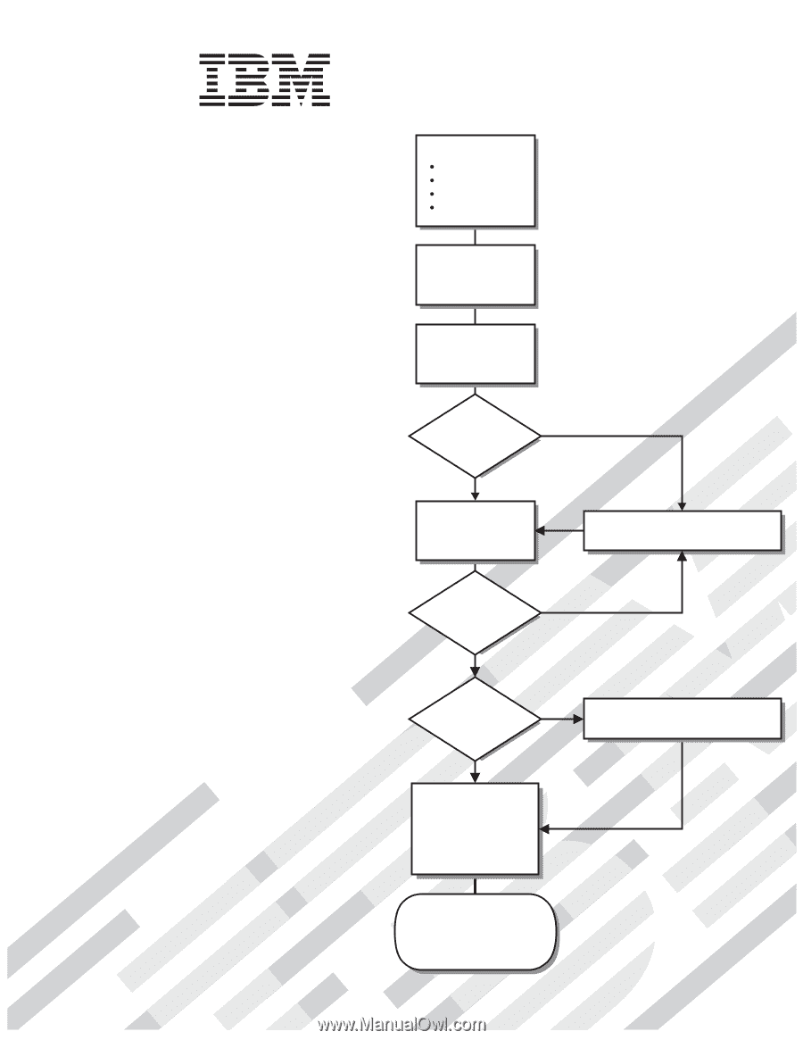
Go to the Server Support
flowchart
Cable the server
and options
Start the server
Install options:
Drives
Microprocessors
Adapters
Memory
Did the server
start correctly?
Yes
No
Use ServerGuide
to set up and
configure hardware
Did configuration
complete?
Use
ServerGuide to
install operating
system?
Install applications,
such as IBM systems
management software
and IBM ServeRAID
programs
System is ready to use.
Go to the Server Support
flowchart to register
and profile your server.
Go to the Web for instructions,
No
Yes
Yes
No
Welcome.
Thank you for buying an
IBM System x server.
This server
contains information for setting
up and configuring your server.
For detailed information about
your server, view the publications
on the
You can also find the most
current information about your
server on the IBM Web site at:
Your server
is based on the X-Architecture
technology, and it features
superior performance, availability,
and scalability.
Documentation CD.
Installation Guide
Installation Guide
Type 8872
and
System x3950
Type 8874
System x3950 E