Icom IC-A210 Installation Guide - Page 1
Icom IC-A210 Manual
 |
View all Icom IC-A210 manuals
Add to My Manuals
Save this manual to your list of manuals |
Page 1 highlights
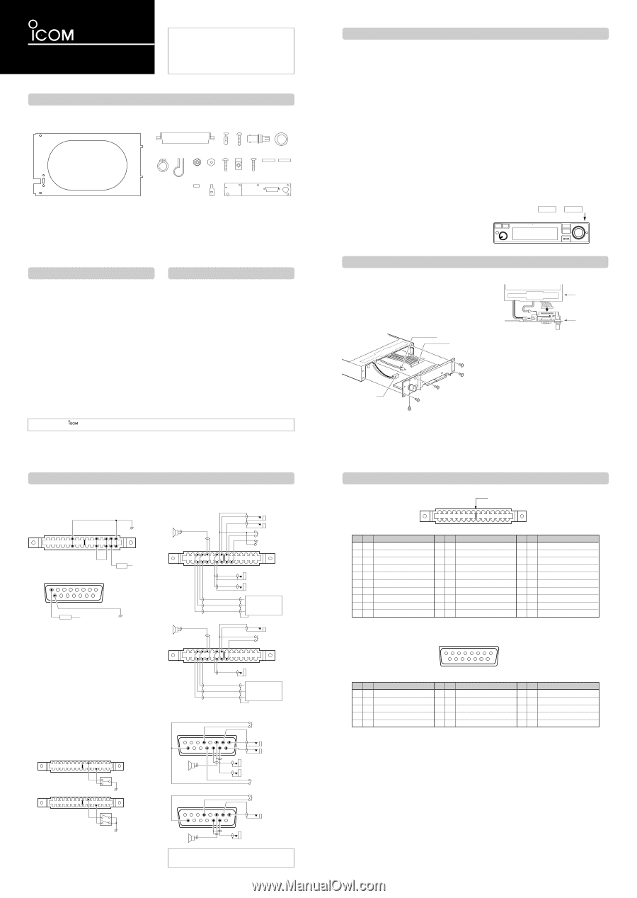
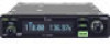
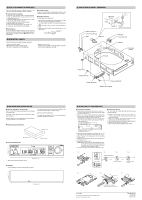
INSTALLATION GUIDE VHF AIR BAND TRANSCEIVER iA210 iA210E Thank you for purchasing the IC-A210/A210E VHF AIR BAND TRANSCEIVER with Icom's state of the art technology. Please read this, not these installation guide and transceiver's instruction manual carefully before installing and operating, not installation and operation. z IC-A210/A210E SUPPLIED ACCESSORIES The following accessories are supplied with the ICA210/A210E. Inspect the quantity of each part carefully. q Make sure you have received all accessories and that there is no shipping damage. w er t y u i o !0 !1 !2 !3 !4 !5 !6 !7 !8 q Mounting bracket 1 w Molex connector (4338-15 1 e Molex terminals (4366-GL 30 r Screws Bind UNC (No. 4 × 12.7 2 t BNC-LP 1 y Washer (Icom washer V 1 u C-shaped ring 1 i Antenna cable clip 1 o Self crimping nut (No. 6 1 !0 Nut (No. 6 1 !1 Screw (No. 6 × 12.7 1 !2 Crimp nuts (No. 6 6 !3 Screws (No. 6 × 12.7 6 !4 COMM1 sticker 1 !5 COMM2 sticker 1 !6 Molex polarizing key 1 !7 Speed nut UNC (No. 6 4 !8 MB-113 1 x IMPORTANT READ THIS, NOT THESE INSTALLATION GUIDE CAREFULLY before attempting to install the ICA210/A210E in an aircraft. This sheet contains important safety instructions for the IC-A210/A210E. NEVER install the transceiver where normal navigation of the aircraft may be hindered. NEVER install an antenna near any aircraft projection, engine, or propeller. INSTALL a circuit breaker between the aircraft battery and the IC-A210/A210E. Check operation after installation. Install the IC-A210/A210E according to the following procedure. c INSTALLATION PROCEDURES q Check the quantity of parts. Refer to z IC-A210/A210E SUPPLIED ACCESSORIES. w Prepare miscellaneous items required for installation. Refer to Miscellaneous items in v PRECAUTIONS. e Prepare required wiring. Refer to n CABLE CONNECTIONS, m CONNECTOR INFORMATION and , MOLEX CONNECTOR ASSEMBLY. r Assemble supplied mounting bracket and other parts. Refer to ⁄0 MOUNTING BRACKET ASSEMBLY. t Cut the mounting hole. Refer to ⁄1 MARKING MOUNTING HOLES. y Mount the IC-A210/A210E into the mounting bracket. Refer to ⁄2 MOUNTING TO THE BRACKET. u Check the IC-A210/A210E operation. Refer to . OPERATION CHECK. Icom, Icom Inc. and the logo are registered trademarks of Icom Incorporated (Japan) in the United States, the United Kingdom, Germany, France, Spain, Rus- sia and/or other countries. Molex is a trademark of Molex Incorporated. n CABLE CONNECTIONS D Power cable wiring Use 2 pairs of #18 AWG wires for power and power grounding connections. For Molex (Front view) _ A F M P R S Power ground 1 6 11 13 14 15 Jumpers For D-sub 15-pin (Front view) 1 8 Circuit breaker (10 A) + 13.8 V DC or 27.5 V DC 9 15 _ Circuit breaker (10 A) + 13.8 V DC or 27.5 V DC Power ground • Circuit breaker To prevent physical damage, a 10 A circuit breaker MUST be installed in the DC power line in the aircraft. Install the circuit breaker in the aircraft breaker panel or instrument panel to ensure easy access during flight. • Ground Connect the transceiver power ground to the airframe ground. • Jumpers Pins 11, M, P and 13 MUST be jumped together with AWG #20 wires or thicker. D Yoke-mounted channel and frequency exchange switches NOTE: Channel and frequency selections are available with the Molex connection only. For the yoke-mounted channel switch and frequency ex- change switch, use a 2-position spring loaded rocker switch or 2 separate momentary push switches. A L S 1 12 15 OR A L S 1 12 15 D Transmit/receive interlock connections When 2 transceivers are installed and both communication antennas are top mounted, pin N MUST be connected to pin 9 of each another transceiver. D Audio line connections Use #24 AWG wires for connections. For Molex (Front view) • Two places with intercom 4 Ω speaker A C DE H JK microphone Jack 1 microphone Jack 2 To PTT switch To Intercom switch PR S 1 3 45 7 8 9 10 15 Headphone jack 1 (to 500 Ω Headphones) Headphone jack 2 To auxiliary audio 1 To auxiliary audio 3 To auxiliary audio 2 Audio control panel • One place 4 Ω speaker A C DE HJ microphone Jack To PTT switch PR S 1 45 78 9 15 Headphone jack (to 500 Ω Headphones) To auxiliary audio 1 To auxiliary audio 3 To auxiliary audio 2 Audio control panel For D-sub 15-pin (Front view) • Two places with intercom 1 4 678 9 4 Ω speaker 12 13 14 15 • One place 1 4 678 To PTT switch microphone Jack 1 microphone Jack 2 Headphone jack 1 (to 500 Ω Headphones) Headphone jack 2 To Intercom switch To PTT switch microphone Jack 9 4 Ω speaker 13 14 Headphone jack (to 500 Ω Headphones) Either intercom or yoke-mounted channel/frequency exchange switch can only be installed. Both switches cannot be installed at the same time. v PRECAUTIONS D Miscellaneous items The following items are required for installation but are NOT supplied with the IC-A210/A210E. q VHF air band antenna for the communication band. w Cables. e Antenna cable with BNC connector (50 Ω). r Switches are mounted on the aircraft yoke. t Headphones (500 Ω). y Low-impedance carbon or dynamic microphone. u Preamplifier for a dynamic microphone. D Transceiver location Select a location which can support the weight of the transceiver. NEVER place the transceiver where normal navigation of the aircraft may be hindered or where it could cause bodily injury. NEVER bend the cables sharply or place the cables too near the aircraft control cables. DO NOT place the transceiver where hot or cold air blows directly on it. AVOID placing the transceiver in areas with temperatures below -20˚C or above +55˚C (-4˚F to +131˚F). D Battery connection NEVER connect the transceiver to a power source using reverse polarity. Reverse polarity will damage the transceiver. To prevent voltage drops, solder or crimp the cable lug when connecting the DC power cable to the power supply. D Antenna NEVER install an antenna near any aircraft projection, engine or propeller. Use a 50 Ω, vertically-polarized, VHF air band antenna. VSWR should be less than 2.5:1. Mount the antenna on an flat metal surface or install a ground plane of at least 120 cm2 (18 in2). D Intercom The intercom function is enabled by wiring and installing a yoke-mounted communications/intercom switch. This function facilitates swift contact between the pilot and co-pilot. 2-pairs of headphones and microphones are required for pilot and co-pilot. D Interlock When 2 transceivers are installed in your aircraft, wiring for a transmit/receive interlock is required. To protect the receiver circuit from extremely strong incoming signals, this function prevents receiving while another transceiver is transmitting. D COMM1 and COMM2 stickers When 2 transceivers are installed, to distinguish them from one another, attach the supplied COMM1 and COMM2 stickers. COMM1 or COMM2 sticker COMM b USING THE MB-113 When installing the IC-A210/A210E into your aircraft, etc., with another connection system using D-sub 15-pin connector, use the supplied MB-113 as described below. D Attachment q Unscrew the 10 bottom screws, then remove the bottom cover from the transceiver. w Unscrew the 5 rear plate screws. e Disconnect the I/O cable connectors and coaxial, J3, J4 and J6, then remove the rear plate from the transceiver. IC-A210 J6 J4 r Connect the I/O cable connectors and coaxial onto the MB-113 as illustrated below. IC-A210 MB-113 t Attach the MB-113 to the transceiver with the 5 rear plate screws. y Replace the removed bottom cover and 10 screws. Plate J3 m CONNECTOR INFORMATION D Molex connector Supplied polarizing key A BCDE F H J K LMNPRS Front view 1 2 3 4 5 6 7 8 9 10 11 12 13 14 15 Pin I/O Description Pin I/O Description A - No connection M In +13.8 V power + B - No connection N - Transmit/receive interlock C In Auxiliary audio 2 + P - No connection D In Auxiliary audio 1 + R In Aircraft power + (13.8/27.5 V) E Out External speaker + (4 Ω/5 W) S In Aircraft power _ F In Aircraft power _ 1 - No connection H Out Headphones audio + (500 Ω/60 mW) 2 - No connection J In Microphone 1+ (600 Ω) 3 In Auxiliary audio 3 + K In Microphone 2+ (600 Ω) 4 In Auxiliary audio 1, 2, 3 _ L In Memory channel switch* 5 In External speaker _ Pin I/O Description 6 In Aircraft power _ 7 Out Headphones audio _ 8 In Mic., Inetrcom mic. and PTT _ 9 In PTT +* 10 In Intercom switch* 11 In +13.8 V power + 12 In Frequency exchange switch* 13 - No connection 14 In Aircraft power + (13.8/27.5 V) 15 In Aircraft power _ *Ground to activate. D D-sub 15-pin 1234567 8 9 10 11 12 13 14 15 Front view Pin I/O Description 1 In Aircraft power + (13.8/27.5 V) 2 - No connection (reserved) 3 Out RS-232 Serial data + (TXD) 4 In PTT +* 5 In Auxiliary audio + Pin I/O Description 6 Out External speaker + (4 Ω/5 W) 7 In Microphone _ 8 In Microphone 1 + (600 Ω) 9 In Aircraft power _ 10 In RS-232 Serial data + (RXD) Pin I/O Description 11 I/O RS-232 Serial data _ 12 In Intercom select switch* 13 Out External speaker and headphones _ 14 Out Headphones audio + (500 Ω/60 mW) 15 In Microphone 2 + (600 Ω) *Ground to activate.
-
 1
1 -
 2
2
 |
 |