Icom IC-A210 Installation Guide - Page 2
Mounting To The Bracket, Marking Mounting Holes - wiring
 |
View all Icom IC-A210 manuals
Add to My Manuals
Save this manual to your list of manuals |
Page 2 highlights
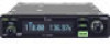
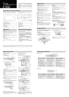
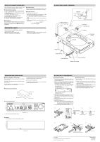
, MOLEX CONNECTOR ASSEMBLY The IC-A210/A210E mates with a Molex connector in the rack mount. Assemble the Molex connector as follows. D Contact terminal assembly q Strip 4 mm (0.16″) from each wire for the contact terminal. w Open the HTR-6115 Molex hand crimper with the en- graved side toward you. e Insert the stripped conductor unit the insulation is even with the side of the crimper facing you. r Clip the conductor tab until a crimp is obtained. t Move the lead to the crimper anvil. y Place the insulating tab section on the crimper anvil. u Crimp again until a sufficient crimp is obtained. D Polarizing key Before installing the Molex connector into the mounting bracket, check the polarizing key position between contacts 8 and 9. Refer to Connector front view in m CONNECTOR INFORMATION. D Contact insertion Insert the contact terminals into the proper location in the connector housing. Push the terminal until a click is heard. D Contact extraction Use the Molex contact ejector tool. q Slip the flat narrow blade of the contact ejector tool under the contact on the mating side of the connector. w Turn the connector upside down to slide the blade into the stop. e When the blade is fully in, pull the lead using moderate force. r Before reinstalling, make sure the tab extends as in the figure below. Molex terminal (4366-GL) Tab . OPERATION CHECK Check the following points after transceiver installation. - Polarity of the power supply. - NO interference caused to other equipment. - NO noise or interference from other equipment. - VSWR is less than 2.5:1. - Communication capability on both the highest and lowest communication frequencies, if possible. ⁄0 MOUNTING BRACKET ASSEMBLY qMounting bracket Coaxial connector oSelf-crimping nut iAntenna cable clip !0Nut tBNC-LP tBNC-LP L-type BNC connector (Purchase locally, if required) yWasher uC-shaped ring !3Screws qMounting bracket !1Screw !2Crimp nuts eMolex terminals wMolex connector rScrews Bind UNC !6Molex polarizing key ⁄1 MARKING MOUNTING HOLES D Notes for making the mounting hole The IC-A210/A210E can be mounted securely in the supplied mounting bracket. Remember to allow adequate space for installation of cables and connectors. When installing 2 or more transceivers in a stack, the mounting trays should be 1.27 mm (0.05″) apart. The mounting bracket has 0.64 mm (0.025″) dimples in the top, bottom, and both sides for proper spacing. Mark and cut the mounting holes. To support the mounting bracket, the rear mounting bosses should be attached to the airframe. D Mounting bracket dimensions 33 mm; 1 5/16″ 260 mm; 10.24″ 160 mm; 6 5/16″ D Front panel dimensions DUAL EC VOL DUAL MEMO GRP RCL MEM 34 mm; 1 11/32″ OFF PUSH TEST Allow space for the front panel as above. iA210 160 mm; 6 5/16″ D Template Cut out dimensions for the mounting bracket as follows. COMM 33 mm; 1 5⁄16″ 160 mm; 6 5⁄16″ ⁄2 MOUNTING TO THE BRACKET D Transceiver installation q Remove the front panel from the main unit, using a 3⁄32″ (2.381mm) allen wrench, then disconnect the flat cable from the front panel. (Fig. 1) w Insert a 3⁄32″ (2.381mm) allen wrench into the hole of the main unit and unscrew the inside lock screw until the inside metal catch touches the chassis hole. (Fig. 2) • Use the metal catch located on bottom side of the transceiver when installing into the existing mounting bracket with MB-113. Main unit front view Use when installing with the original mounting bracket. D Transceiver removal The IC-A210/A210E is easily removed from the mounting bracket, if required. q Remove the front panel from the main unit, using a 3⁄32″ (2.381mm) allen wrench, then disconnect the flat cable from the front panel. w Insert a 3⁄32″ (2.381mm) allen wrench into the hole of the main unit and unscrew the inside lock screw. e Slowly pull the transceiver out from the mounting bracket. r Connect the flat cable to the front panel. t Attach the front panel and tighten the allen screws. Using this hole when installing with the MB-113. e Rotate the lock screw clockwise 4 revolutions (Fig. 3), and then rotate counterclockwise a quarter revolution. (Fig. 4) r Insert the main unit (transceiver) into the mounting bracket. (Fig. 5) t Screw the lock screw to fix the main unit (transceiver) to the bracket. (Fig. 6) y Connect the flat cable. (Fig. 7) NOTE: Make sure that the flat cable between the transceiver and front panel is securely connected. The transceiver may not function properly when loose or when a wrong connection is made. u Attach the front panel and re-screw the allen bolts (Fig. 7). Fig. 1 Fig. 2 Fig. 3 • Metal catch position Metal catch Screw 4 revolutions Fig. 4 Surface Unscrew a quarter revolution Fig. 5 Fig. 6 Fig. 7 Clockwise: For installation. Counterclockwise: For removal. 1-1-32 Kamiminami, Hirano-ku, Osaka 547-0003, Japan Printed on recycled paper with soy ink. The flat cable A-6602H-2EX Printed in Japan © 2007 Icom Inc.
-
 1
1 -
 2
2
 |
 |