Icom IC-F6061D Instruction Manual - Page 20
CONNECTION AND MAINTENANCE, Rear panel connection
 |
View all Icom IC-F6061D manuals
Add to My Manuals
Save this manual to your list of manuals |
Page 20 highlights
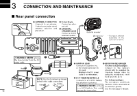
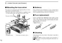
3 CONNECTION AND MAINTENANCE ■ Rear panel connection Antenna q ANTENNA CONNECTOR Connects to an antenna. Contact your dealer about antenna selection and placement. w D-Sub 25-pin Connect an external unit. e EXTERNAL SPEAKER JACK Connect a 4-8 ˘ external speaker. w q Optional speaker Microphone* * The type is different depending on the transceiver's version. e r R WARNING! NEVER remove t the fuse-holder from the DC power cable. t IGNITION LEAD r MICROPHONE HANGER Connects to a ignition line. For Non-self ground type: Red R Do not put a pressure to Connect to the vehicle's y this lead. ground with the supplied mi- Black Binding to the DC power cable is recommended. crophone hanger cable for using the microphone on/off 12V Battery 15 NOTE: Use the terminals as shown below for the cable connections. Crimp Solder y DC POWER RECEPTACLE Connects to a 12 V DC battery. Pay attention to polarities. R WARNING! NEVER connect to a 24 V battery. This could damage the transceiver. hook functions. (p. 1) For Self ground type: The microphone on/off hook functions can be used without the vehicle's ground. See the next page for details.
-
 1
1 -
2
-
3
-
4
-
5
-
6
-
7
-
8
-
9
-
10
-
11
-
12
-
13
-
14
-
 15
15 -
 16
16 -
 17
17 -
 18
18 -
 19
19 -
 20
20 -
 21
21 -
 22
22 -
 23
23 -
 24
24 -
 25
25 -
26
-
27
-
28
-
29
-
30
-
31
-
32
 |
 |
