Icom VE-PG4 Instruction Manual - Page 1
Icom VE-PG4 Manual
 |
View all Icom VE-PG4 manuals
Add to My Manuals
Save this manual to your list of manuals |
Page 1 highlights
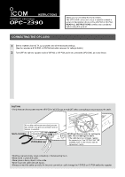
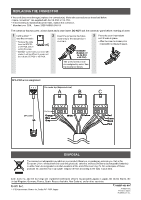
INSTRUCTIONS CONNECTION CABLE OPC-2390 Thank you for choosing this Icom product. The OPC-2390 connection cable is used to connect a serial communication device to the VE-PG3 or VE-PG4. READ ALL INSTRUCTIONS carefully and completely before using this product. CONNECTING THE OPC-2390 1 Set the repeater channel, TX output power, and other necessary settings. (See the repeater and VE-PG3 or VE-PG4 instruction manuals for settings details.) 2 Turn OFF the both the repeater and the VE-PG3 or VE-PG4, and then connect the OPC-2390, as shown below. VE-PG4 (Rear view) Icom's repeater (IC-FR5000/IC-FR6000 series) A1~A4 B1~B4 C1~C4 A1~A4 B1~B4 C1~C4 A1~A4 B1~B4 C1~C4 A1~A4 B1~B4 C1~C4 A BC Be sure to insert the connectors top side up. To the accessory connector A BC 1234 Top A Bottom OPC-2390 • This is an example of connecting a repeater to the [EXT1] port. CAUTION • Verify that both the repeater and the VE-PG3 or VE-PG4 are turned OFF when connecting or disconnecting the cable. When other cables are connected, you can use needle-nose pliers to carefully insert or remove connectors. Needle-nose pliers Connector body VE-PG4 (Rear view) NEVER pull the connector by holding the cable. This will damage the cable. *If the cable becomes damaged, replace the connector(s). See "REPLACING THE CONNECTOR" on the reverse side for replacement details. • Hold the connector body when connecting or disconnecting them. • Never bend or pinch the cable. • Never place a heavy object on the cable. • Never touch the cable with wet hands. • Always connect the cable correctly. An incorrect connection could damage the VE-PG3 or VE-PG4 and/or the repeater.
-
 1
1 -
 2
2
 |
 |