Image Fitness 20.0 Vt Treadmill English Manual - Page 9
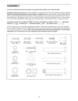
M10 Flat Washer 14, and an M10 Star Washer
 |
View all Image Fitness 20.0 Vt Treadmill manuals
Add to My Manuals
Save this manual to your list of manuals |
Page 9 highlights
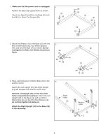
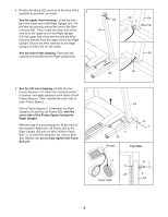
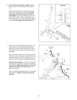
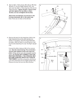
6. See the left inset drawing in step 5. Identify 6 the outer side of the remaining Frame Spacer (11). Hold the Frame Spacer (11) between the Left Upright (53) and the Lift Frame (23), with the outer side of the Frame Spacer facing the Left Upright. Attach the Left Upright to the Lift Frame with an M10 x 60mm Patch Bolt (1), an M10 Flat Washer (14), and an M10 Star Washer (9); do not fully tighten the Patch Bolt yet. 53 Top View 1 14 11 9 23 53 9 14 1 11 23 7. Set the Console Assembly (91) face down on a soft surface to avoid scratching the Console Assembly. Hold the Right Handrail (33), which has a large hole in one side, near the Console Assembly. Next, insert the console wire and the tie into the hole in the side of the Right Handrail (33). Using needlenose pliers, pull the console wire out of the hole near the bracket on the Right Handrail. See the inset drawing. Insert the included wire tie through the indicated small hole in the Right Handrail (33). Make sure that the console wire has been secured to the side shown, and tighten the wire tie. Then, set the Right Handrail (33) on the Console Assembly (91). Make sure that no wires are pinched. 7 Console Wire Tie Bracket 33 91 Large Hole 33 Small Hole Wire Tie 9
-
 1
1 -
2
-
3
-
 4
4 -
 5
5 -
 6
6 -
 7
7 -
 8
8 -
 9
9 -
 10
10 -
 11
11 -
 12
12 -
 13
13 -
 14
14 -
15
-
16
-
17
-
18
-
19
-
20
-
21
-
22
-
23
-
24
-
25
-
26
-
27
-
28
 |
 |
