Image Fitness 5.0 Bench User Manual - Page 10
Do not overtighten the M10 Nylon Locknuts
 |
View all Image Fitness 5.0 Bench manuals
Add to My Manuals
Save this manual to your list of manuals |
Page 10 highlights
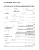
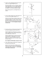
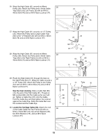
14. Attach the Bench Frame (14) to the Back Leg (39) with an M10 x 78mm Bolt (70), two M10 x 14 164mm Bolts (71), an M10 Washer (79), and three M10 Nylon Locknuts (77). Do not tighten the Nylon Locknuts yet. 77 70 39 14 71 79 77 15. Attach the Leg Lever Bumper (54) to the Front Leg (18) with the M4 x 19mm Screw (68) and an M5 Washer (92). Press a 38.1mm x 76.2mm Inner Cap (49) and a 2" x 3" Inner Cap (50) into the Leg Lever (19). Lubricate an M10 x 102mm Bolt (91). Attach the Leg Lever (19) to the Front Leg (18) with the Bolt and an M10 Nylon Locknut (77). Do not overtighten the Nylon Locknut; the Leg Lever must be able to pivot easily. 15 49 50 77 19 54 68 92 91 18 Lubricate 16. Press four 25.4mm x 38.1mm Inner Caps (45) 16 into the Backrest Frame (16). Orient the Backrest (38) as shown. Attach the 38 Backrest to the Backrest Frame (16) with four M6 x 16mm Bolts (72). 45 17. Press two 38mm Square Inner Caps (44) into the ends of the Support Leg (13). Lubricate an M10 x 154mm Bolt (69). Attach the Support Leg (13) to the Backrest Frame (16) with the Bolt, two M10 Washers (79), and an M10 Nylon Locknut (77). Lubricate an M10 x 164mm Bolt (71). Attach the Support Leg (13) to the Back Leg (39) with the Bolt, two M10 Washers (79), and an M10 Nylon Locknut (77). Lubricate two M10 x 45mm Bolts (76). Attach the Backrest Frame (16) to the Sliding Seat Frame (15) with the Bolts, two M10 Washers (79), and two M10 Nylon Locknuts (77). Do not overtighten the M10 Nylon Locknuts (77); the Support Leg (13) and the Backrest Frame (16) must be able to pivot easily. 16 72 45 72 17 77 79 76 77 79 16 76 15 44 77 79 79 69 44 13 39 79 71 10
-
 1
1 -
2
-
3
-
4
-
 5
5 -
 6
6 -
 7
7 -
 8
8 -
 9
9 -
 10
10 -
 11
11 -
 12
12 -
 13
13 -
 14
14 -
 15
15 -
16
-
17
-
18
-
19
-
20
-
21
-
22
-
23
-
24
-
25
-
26
 |
 |
