Image Fitness 5.2 Bench English Manual - Page 12
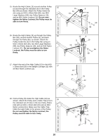
Note: Do not overtighten the Nylon Locknut
 |
View all Image Fitness 5.2 Bench manuals
Add to My Manuals
Save this manual to your list of manuals |
Page 12 highlights
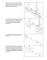
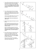
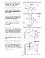
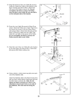
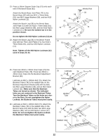
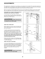
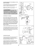
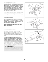
23. Press a 50mm Square Outer Cap (73) onto each end of the Bench Base (62). Attach the Bench Base Joint Plate (72) to the Bench Base (62) with two M10 x 70mm Bolts (91), two M10 Large Washers (58), and two M10 Nylon Locknuts (11). Attach the Bench Leg (59) to the Bench Base Joint Plate (72) with two M10 x 70mm Bolts (91), two M10 Large Washers (58), and two M10 Nylon Locknuts (11). Be sure the welded nut is in the position shown. Do not tighten the M10 Nylon Locknuts (11) yet. 24. Attach the Bench Leg (59) to the Bench Frame (61) with two Thick Joint Plates (71), four M10 x 70mm Bolts (91), and four M10 Nylon Locknuts (11). Note: Tighten all the M10 Nylon Locknuts (11) used in steps 22-24. 23 Welded Nut 59 58 91 62 58 11 73 58 72 24 91 91 58 73 71 61 71 59 11 25. Press two 25mm x 40mm Inner Caps (79) into each Backrest Tube (78). Press two 25mm x 40mm Inner Caps into the Backrest Adjustment Bracket (83). Lubricate an M10 x 190mm Bolt (75). Attach the Backrest Tubes (78) to the welded tube on the Backrest Adjustment Bracket (83) with the Bolt, two M10 Large Washers (58), and an M10 Nylon Locknut (11). Make sure that the Backrest Tubes are turned as shown. The indicated holes are not centered in the Backrest Tubes. Turn the Backrest Tubes so the holes are closer to the floor. Do not overtighten the Nylon Locknut; the Backrest Tubes must pivot easily. 26. Lubricate an M10 x 190mm Bolt (75). Attach the Backrest Tubes (78) to the welded tube on the Bench Frame (61) with the Bolt, two M10 Large Washers (58), and an M10 Nylon Locknut (11). Note: Do not overtighten the Nylon Locknut; the Backrest Tubes must pivot easily. 25 Lubricate 78 79 58 75 Holes 11 58 79 83 Welded Tube 79 26 Lubricate 58 75 78 Welded Tube 58 11 61 12
-
 1
1 -
2
-
3
-
4
-
5
-
6
-
 7
7 -
 8
8 -
 9
9 -
 10
10 -
 11
11 -
 12
12 -
 13
13 -
 14
14 -
 15
15 -
 16
16 -
 17
17 -
18
-
19
-
20
-
21
-
22
-
23
 |
 |
