Image Fitness 5.5 Bench English Manual - Page 10
and a M10 Nylon Locknut 29.
 |
View all Image Fitness 5.5 Bench manuals
Add to My Manuals
Save this manual to your list of manuals |
Page 10 highlights
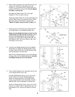
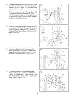
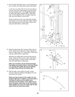
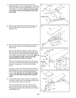
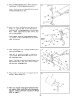
14. Pull the High Cable (84) down in the indicated loca- 14 tion, so there is no slack at the ends of the Cable. Locate the Low Cable (25), which has two balls on one end. Insert the metal-sleeve end of the Cable into the indicated hole in the Weight Guide Base (4). Attach the Cable using an M10 x 72mm Bolt 84 (34), two M10 Washers (37), two 28mm Spacers (40), and a M10 Nylon Locknut (29). Route the ball-end of the Low Cable (25) through the bracket on the Center Base (2). Attach a Pulley (24) inside the bracket using a M10 x 45mm Bolt (32) and a M10 Nylon Locknut (29). 25 24 37 40 29 2 15. Wrap the High Cable (84) around a Pulley (24) as shown. Attach the Pulley and a Cable Trap (23) to the two Pulley Plates (17) using a M10 x 45mm Bolt (32) and a M10 Nylon Locknut (29). Wrap the Low Cable (25) around a Pulley (24) as shown. Attach the Pulley and a Cable Trap (23) to the Pulley Plates (17) using a M10 x 45mm Bolt (32) and a M10 Nylon Locknut (29). Make sure the Bolts (32) are inserted through the highest and lowest holes in the Pulley Plates (17), and that the Cables (25, 84) are between the Cable Traps (23) and the Pulleys (24). 16. Wet the ends of the Lat Bar (45) with a small amount of lubricant. Slide the Handgrips (47) onto the ends of the Lat Bar. Make sure that all parts of the weight rack are properly tightened. In addition, pull each cable a few times to make sure the cables move smoothly over the pulleys. If the cables do not move smoothly, locate and correct the problem. When weights are used, the cables may be damaged if they are incorrectly routed. 15 84 17 29 25 16 47 4 40 37 34 32 24 23 17 32 23 45 47 10
-
 1
1 -
2
-
3
-
4
-
 5
5 -
 6
6 -
 7
7 -
 8
8 -
 9
9 -
 10
10 -
 11
11 -
 12
12 -
 13
13 -
 14
14 -
 15
15 -
16
-
17
-
18
-
19
-
20
-
21
-
22
 |
 |
