Image Fitness 5.5 English Manual - Page 12
Locknut; the Seat Mounting Bracket must pivot
 |
View all Image Fitness 5.5 manuals
Add to My Manuals
Save this manual to your list of manuals |
Page 12 highlights
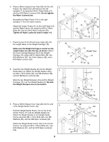
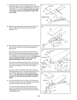
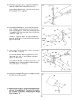
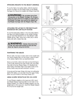
21. Lubricate a M10 x 192mm Bolt (66). Attach the Backrest Tubes (71) to the welded tube on the Bench Frame (52) with the Bolt, two M10 Washers (37), and a M10 Nylon Locknut (29). Note: Do not over tighten the Nylon Locknut; the Backrest Tubes must pivot easily. 21 Lubricate 37 66 71 Welded Tube 52 37 29 22. Attach the Backrest (60) to the Backrest Tubes (71) 22 with four M6 x 52mm Screws (51) and four M6 Washers (74). 60 71 23. See the inset drawing. Press the 20mm x 40mm Inner Cap (77) into the open end of the Seat Mounting Bracket (67). See the inset drawing. Lubricate a M10 x 68.5mm Bolt (75). Attach the Seat Adjustment Bracket (80) to the indicated side of the Seat Mounting Bracket (67) with the Bolt and a M10 Nylon Locknut (29). Note: Do not over tighten the Nylon Locknut; the Seat Adjustment Bracket must pivot easily. Place the Seat Mounting Bracket (67) on the Bench Frame (52) so that the Seat Adjustment Bracket (80) fits over the welded pin on the side of the Bench Frame. 23 Lubricate 80 34 Welded Pin 52 Lubricate a M10 x 72mm Bolt (34). Attach the Seat Mounting Bracket (67) to the indicated bracket on the Bench Frame (52) with the Bolt and a M10 Nylon Locknut (29). Note: Do not over tighten the Nylon Locknut; the Seat Mounting Bracket must pivot easily. 24 59 24. Turn the Seat (59) as shown. Attach the wide end of the Seat to the bracket on the Seat Mounting Bracket (67) with two M6 x 16mm Screws (50). Bracket 67 74 51 67 Lubricate 80 67 75 29 77 29 Tilt the Seat Mounting Bracket (67) upwards and attach the narrow end of the Seat (59) to the Seat Mounting Bracket with a M6 x 35mm Screw (78) and an M6 Washer (74). 74 50 78 12
-
 1
1 -
2
-
3
-
4
-
5
-
6
-
 7
7 -
 8
8 -
 9
9 -
 10
10 -
 11
11 -
 12
12 -
 13
13 -
 14
14 -
 15
15 -
 16
16 -
 17
17 -
18
-
19
-
20
-
21
-
22
 |
 |
