Insignia NS-HTIB51A User Manual (English) - Page 8
Display, Subwoofer - composite
 |
View all Insignia NS-HTIB51A manuals
Add to My Manuals
Save this manual to your list of manuals |
Page 8 highlights
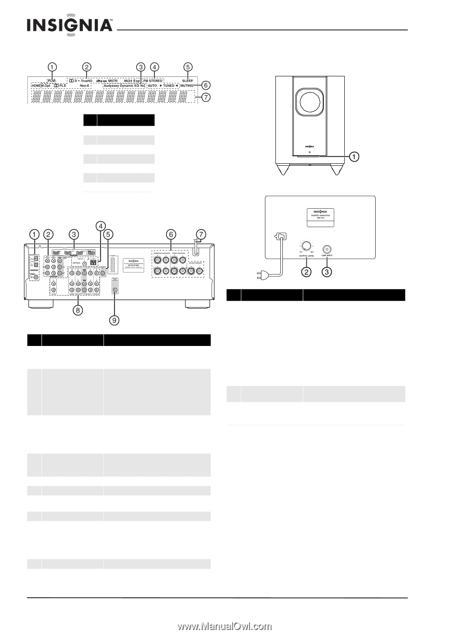
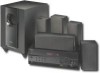
Display Back # Indicator 1 Audio input indicator 2 Listening mode indicator 3 Audyssey indicators 4 Tuning indicators 5 SLEEP indicator 6 MUTING indicator 7 DIGITAL display Insignia NS-HTIB51A 5.1 Channel Home Theater System Subwoofer Front Back # Description Function 1 DIGITAL IN jacks Plug the optical digital cable from a game (1) or TV/CD (2) into the upper jacks, or the coaxial digital cable from a BD/DVD into the lower jack. 2 COMPONENT video jacks Plug the cables from a component video source into the #1 (BD/DVD) or #2 (CBL/SAT) jacks. Plug the cables to a component video monitor into the OUT jacks. The jacks are color coded (red, green, and blue) to correspond to the cable connectors. 3 HDMI jacks Plug the HDMI signal input cable from a GAME (IN3), cable/satellite box (IN2), or a BD/DVD player (IN1). Plug the HDMI output signal cable to a TV or monitor into the OUT jack. 4 ANTENNA connectors Connect a 75 ohm FM antenna to the coaxial connector or an AM loop antenna to the wire connectors. 5 MONITOR OUT V (Video) Connect this jack to a TV monitor. 6 FRONT SPEAKERS Connect the front speakers to these jacks. SURROUND SPEAKERS Connect the left and right surround speakers and CENTER SPEAKER the center speaker to these connectors. 7 AC power cord Plug this cord into an AC power outlet. 8 Composite Video and Plug the composite video and audio L/R output Audio L/R jacks cables from the indicated devices into these jacks. For video recording, plug the composite video and audio L/R input cables to a VCR or DVR into the OUT jacks 9 SUBWOOFER Connect the subwoofer to this jack. # Description 1 Standby/On indicator 2 OUTPUT LEVEL control 3 LINE INPUT jack Function Red: Subwoofer in standby mode Blue: Subwoofer on With the auto standby function, the subwoofer automatically turns on when an input signal is detected in standby mode. When there is no input signal, the subwoofer automatically enters standby mode. Note: The auto standby function turns the subwoofer on when the input signal exceeds a certain level. If the auto standby function does not work reliably, try slightly increasing or decreasing the subwoofer output level on the receiver This control is used to adjust the volume of the subwoofer. This jack should be connected to the subwoofer pre-out on the AV receiver with the supplied RCA cable. 4 www.insigniaproducts.com
-
 1
1 -
2
-
 3
3 -
 4
4 -
 5
5 -
 6
6 -
 7
7 -
 8
8 -
 9
9 -
 10
10 -
 11
11 -
 12
12 -
 13
13 -
14
-
15
-
16
-
17
-
18
-
19
-
20
-
21
-
22
-
23
-
24
-
25
-
26
-
27
-
28
-
29
-
30
-
31
-
32
-
33
-
34
-
35
-
36
-
37
-
38
-
39
-
40
 |
 |