Intel 850E User Manual
Intel 850E - P4 ATX 533MHzFSB USB2 LAN Manual
 |
UPC - 735858158121
View all Intel 850E manuals
Add to My Manuals
Save this manual to your list of manuals |
Intel 850E manual content summary:
- Intel 850E | User Manual - Page 1
® P4T-M Intel® 850 Micro-ATX Motherboard USER'S MANUAL ASUS P4T-M User's Manual 1 - Intel 850E | User Manual - Page 2
revision number. For previous or updated manuals, BIOS, drivers, or product release information, contact ASUS at http://www.asus.com.tw or through any of the means indicated on the following page. SPECIFICATIONS AND INFORMATION CONTAINED IN THIS MANUAL ARE FURNISHED FOR INFORMATIONAL USE ONLY, AND - Intel 850E | User Manual - Page 3
Email: [email protected] Technical Support MB/Others (Tel): +886-2-2890 Email: [email protected] Technical Support Fax: +1-510-608-4555 Support Hotline: MB/Others: +49-2102-9599-0 Notebook: +49-2102-9599-10 Fax: +49-2102-9599-11 Support (Email): www.asuscom.de/de/support (for online support - Intel 850E | User Manual - Page 4
7 1.1 How This Manual Is Organized 7 1.2 Item Checklist 7 2. FEATURES 8 2.1 The ASUS P4T-M 8 2.2 P4T-M Motherboard Components 12 3. HARDWARE SETUP 14 3.1 P4T-M Motherboard Layout 14 3.2 Layout Contents 15 3.3 Getting Started 16 3.4 System Memory 17 3.5.1 CPU Installation 19 3.5 Central - Intel 850E | User Manual - Page 5
CONTENTS 4.5.2 Hardware Monitor 64 4.6 Boot Menu 65 4.7 Exit Menu 67 5. SOFTWARE SETUP 69 5.1 Install Operating System 69 5.2 Start Windows 69 5.3 P4T-M Motherboard Support CD 70 6.1 ASUS Live Update 72 6. SOFTWARE REFERENCE 73 6.2 ASUS PC Probe 73 6.3 CyberLink PowerPlayer SE 78 6.4 - Intel 850E | User Manual - Page 6
if not installed and used in accordance with manufacturer's instructions, may cause harmful interference to radio communications. However, and receiver. • Connect the equipment to an outlet on a circuit different from that to which the receiver is connected. • Consult the 6 ASUS P4T-M User's Manual - Intel 850E | User Manual - Page 7
(2) ASUS C-RIMM Continuity RIMM (1) ASUS 2-port USB connector set with bracket (1) I/O port bracket (1) Bag of spare jumpers (1) Support drivers and utilities (1) This Motherboard User's Manual (1) CPU Heatsink Retention Module (1) Quick Setup Manual (1) Reference Card Optional Items ASUS IrDA - Intel 850E | User Manual - Page 8
fastest processors. 2.1.1 Specifications • Intel Processor Support: Intel Socket 423 Pentium® 4 processors. • Intel 850 Chipset: Features the Intel® 850 chipset (Memory Controller Hub, I/O Controller Hub, and Firmware Hub) with support for AGP 4X mode; 400MHz Front Side Bus (FSB); and dual channel - Intel 850E | User Manual - Page 9
two high-speed UART compatible serial ports and one parallel port with EPP and ECP capabilities. UART2 can also be directed from COM2 to the Infrared Module for wireless connections. • Enhanced ACPI & Anti-Boot Virus Protection: Programmable BIOS (Flash EEPROM), offering enhanced ACPI for Windows 98 - Intel 850E | User Manual - Page 10
Performance: This motherboard supports the new generation memory, Rambus Dynamic Random Access Memory (RDRAM). drivers and installation procedures for Windows 95/NT and later. Color-coded connectors and descriptive icons make identification easy as required by PC 99. 10 ASUS P4T-M User's Manual - Intel 850E | User Manual - Page 11
motherboard components. Voltage specifications are more critical for future processors, so monitoring is necessary to ensure proper system configuration and management. • System Resources Alert: Today's operating systems, such as Windows 98/ Millenium, and Windows NT/2000, require much more memory - Intel 850E | User Manual - Page 12
-M Motherboard Components See opposite page for locations. Location Processor Support Socket 423 for Pentium 4 Processors 1 Chipsets Intel 850 Memory Controller Hub (MCH 2 Intel I/O Controller Hub 2 (ICH2 11 4Mbit Firmware Hub (FWH 9 Yamaha Audio Chipset 16 Main Memory Maximum 2GB support - Intel 850E | User Manual - Page 13
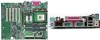
2. FEATURES Component Locations 2. FEATURES 2.2.1 Component Locations 1 2 3 45 6 7 26 25 24 23 22 21 20 19 18 17 16 15 14 13 12 11 10 9 8 ASUS P4T-M User's Manual 13 - Intel 850E | User Manual - Page 14
SETUP 3.1 P4T-M Motherboard Layout PS/2KBMS T: Mouse B: Keyboard Bottom: Top: USB1 RJ-45 USB2 COM1 24.4cm (9.60in) CPU_FAN Multi I/O ATX12V ATX Power Connector PARALLEL PORT Socket 423 PWR_FAN SECONDARY IDE GAME_AUDIO IEEE1394 Line Out Line In 1394HEAD3 Intel 850 Memory Controller Hub - Intel 850E | User Manual - Page 15
SETUP 3.2 Layout Contents Expansion 1) RIMMA1/A2/B1/B2 2) CPU 3) HEATSINK 3) PCI1/2/3 4) AGP 4X p.17 184-Pin System Memory Support p.19 Central Processing Unit (CPU) p.20 CPU Heatsink Retention Module Installation p.23 32-bit PCI Bus Expansion Slots p.25 Accelerated Graphics Port (AGP 4X) Slot - Intel 850E | User Manual - Page 16
Motherboard Settings • Install Memory Modules • Install the Central Processing Unit (CPU) • Install Expansion Cards • Connect Ribbon Cables, Panel Wires, and Power Supply WARNING! Computer motherboards or to a metal object, such as the power supply case. 3. Hold components by the edges and try not to - Intel 850E | User Manual - Page 17
Memory 3. HARDWARE SETUP 3.4 System Memory NOTE: No hardware or BIOS setup is required after adding or removing memory. This motherboard has four 184-pin Rambus Inline Memory Modules (RIMM) sockets. These sockets support 64Mbit, 128Mbit, and 256Mbit Direct RDRAM technologies. Location Memory - Intel 850E | User Manual - Page 18
the ejectors in the open position (as shown), push down gently but firmly on the memory module until it snaps into place. The guides on the socket's ejectors should go through the two mounting notches on the module and the the modules to cool off before removing them. 18 ASUS P4T-M User's Manual - Intel 850E | User Manual - Page 19
Central Processing Unit (CPU) The motherboard provides a ZIF Socket for the P4 Socket 423 CPU. The CPU that came with the motherboard should have a fan opened (90 to 100 degrees). 2. Insert the CPU with the correct orientation. The gold arrow of the CPU must be oriented toward the outer corner of the - Intel 850E | User Manual - Page 20
brace with two separate retaining clips may be included with this package, below right. Both types of supports may be affixed to the motherboard using the plastic plugs and shown in #2 below. 3. H/W SETUP Heatskink Built-in retaining clips 2. Four black plastic collars and four white plastic - Intel 850E | User Manual - Page 21
support braces have built-in retaining clips, right. Close and snap the clips into the locked position. With the added weight of the CPU fan and heatsink locking brace, no extra force is required to keep the CPU in place. 2. Connect the CPU fan cable to the fan connector. (See 3.1 Motherboard - Intel 850E | User Manual - Page 22
clip to the protruding black tab on the end of the plastic heatsink support base. 3. Push down on the levered end of the heatsink retaining clip until it locks into place. 4. Connect the CPU fan cable to the fan connector. (See 3.1 Motherboard Layout / 3.8 Connectors). 22 ASUS P4T-M User's Manual - Intel 850E | User Manual - Page 23
may need to install expansion cards. The motherboard has five PCI expansion slots to support these cards. Follow the steps in the next Change the necessary BIOS settings, if any. (see section 4.4.3 PCI Configuration to change the settings.) 7. Install the necessary software drivers for the expansion - Intel 850E | User Manual - Page 24
Table for this Motherboard PCI slot 1 PCI slot 2 PCI slot 3 AGP slot USB HC0 USB HC1 SMB AC drivers support "Share IRQ" or that the cards do not need IRQ assignments. Conflicts will arise between the two PCI groups that will make the system unstable or cards inoperable. 24 ASUS P4T-M User's Manual - Intel 850E | User Manual - Page 25
motherboard provides an accelerated graphics port (AGP 4X) to support a new generation of AGP graphics cards with ultra-high memory bandwidth. P4T-M P4T-M Accelerated Graphics Port (AGP) IMPORTANT: Only 1.5V AGP cards are supported to use. 3. H/W SETUP Expansion Cards ASUS P4T-M User's Manual 25 - Intel 850E | User Manual - Page 26
Motherboard Layout. Placing jumper caps over these connector pins will cause damage to your motherboard. IMPORTANT: Ribbon cables should always be connected SETUP Connectors 2) PS/2 Keyboard Connector (Purple 6-pin PS2KBMS) This connection is for a standard keyboard using an PS/2 plug (mini DIN). - Intel 850E | User Manual - Page 27
Port (see 4.4.2 I/O Device Configuration). NOTE: Serial printers must be connected to the serial port. Parallel (Printer) Port (25-pin female) A second serial header is available using a serial port bracket connected from the motherboard to an expansion slot opening. See Onboard Serial Port 1/2 in - Intel 850E | User Manual - Page 28
) must be Enabled to use these ports. USB 1 Universal Serial Bus (USB) 2 6) Fast-Ethernet Port Connector (RJ45) (optional) The RJ45 connector is optional at the time of purchase and is located on top of the USB connectors. The connector allows the motherboard to connect to a Local Area Network (LAN - Intel 850E | User Manual - Page 29
Floppy Disk Drive Connector (34-1pin FLOPPY) This connector supports the provided floppy drive ribbon cable. After connecting the single end to the board, connect the two plugs on the other end to the floppy drives PIN 1. P4T-M PIN 1 P4T-M Floppy Disk Drive Connector ASUS P4T-M User's Manual 29 - Intel 850E | User Manual - Page 30
that non-UltraDMA/100 devices be connected to the secondary IDE connector. If you install two hard disks, you must configure the second drive to Slave mode. Please refer to your hard disk documentation for the jumper settings. BIOS now supports specific device bootup (see 4.6 Boot Menu). (Pin - Intel 850E | User Manual - Page 31
IEEE-1394 Headers (8-pin 1394HEAD2/1394HEAD3) (optional) These headers support an IEEE-1394 serial connector cable set that mounts to a standard expansion slot in the computer case. 1394-compliant internal fixed disk drives may also be connected to these headers. P4T-M P4T-M IEEE-1394 Headers +12V - Intel 850E | User Manual - Page 32
CPU (CPU_FAN), Power Supply (PWR_FAN) Fan Connectors (3 pins) These connectors support should be ground. Connect the fan's plug Intel LDCM. WARNING! The CPU and/or motherboard will overheat if there is no airflow across the CPU and onboard heatsinks. Damage may occur to the motherboard and/or the CPU - Intel 850E | User Manual - Page 33
P4T-M Digital Audio Interface 1 +5V SPDIFOUT Ground SPDIFOUT 17) Wake-On-LAN Connector (3-pin WOL) This connector supports a LAN card with a Wake-On-LAN output, such as the ASUS PCI-L101 Ethernet card (see 7. Appendix). The connector powers up the system when a wakeup packet or signal is received - Intel 850E | User Manual - Page 34
shown in Back View and connect a ribbon cable from the module to the motherboard's SIR connector according to the pin definitions. Front View Back View IR +5V (NC) IRRX GND IRTX 1 P4T-M P4T-M Infrared Module Connector IRTX +5V GND (NC) IRRX 19) Front Panel Connectors (24-1 pin AFPANEL) This - Intel 850E | User Manual - Page 35
powering up if your power supply is inadequate. For WakeOn-LAN support, your ATX power supply (minimum recommended wattage: 230watts) must supply the cabinet's IDE activity LED. Read and write activity by devices connected to the Primary/Secondary IDE and Primary/ Secondary ATA100 connectors will - Intel 850E | User Manual - Page 36
ATX power supply. P4T-M System Panel Connectors 22) System Power LED Lead (3-1 pin PWRLED) This 3-1 pin connector connects the system power LED, which requires an ACPI OS and driver support. 26) System Management Interrupt Lead (2-pin SMI) This allows the user to manually place the system into a - Intel 850E | User Manual - Page 37
power supplies, you need to switch on the power supply as well as press the ATX power switch on the front of the case. 6. The power LED on the front panel of the system case will light. For ATX power supplies, the system LED will light when the ATX power switch is pressed. The LED - Intel 850E | User Manual - Page 38
instructions in 4. BIOS SETUP. * Powering Off your computer: You must first exit or shut down your operating system before switching off the power switch. For ATX power supplies, you can press the ATX power switch after exiting or shutting down your operating system. If you use Windows after Windows - Intel 850E | User Manual - Page 39
motherboard BIOS along with a Flash Memory Writer utility (AFLASH.EXE) to a bootable floppy disk in case you need to reinstall the BIOS later. AFLASH.EXE is a Flash Memory Writer utility that updates the BIOS by uploading a new BIOS in Windows and will not work with certain memory drivers that may - Intel 850E | User Manual - Page 40
Procedures WARNING! Only update your BIOS if you have problems with your motherboard and you know that the new BIOS revision will solve your problems. Careless updating can result in your motherboard having more problems! 1. Download an updated ASUS BIOS file from the Internet (WWW or FTP) (see ASUS - Intel 850E | User Manual - Page 41
if the problem still persists, update the original BIOS file you saved to disk above. If the Flash Memory Writer utility was not able to successfully update a complete BIOS file, your system may not be able to boot up. If this happens, your system will need servicing. ASUS P4T-M User's Manual 41 - Intel 850E | User Manual - Page 42
Setup Program This motherboard supports a programmable EEPROM that can be updated using the provided utility as described in 4.1 Managing and Updating Your BIOS. The utility is used if you are installing a motherboard, reconfiguring your system, or prompted to "Run Setup". This section describes - Intel 850E | User Manual - Page 43
the legend bar with their corresponding alternates and functions. Navigation Key(s) or ← or → (keypad arrow) or spacebar Function Description Displays the General Help screen from anywhere in the BIOS Setup Jumps to the Exit menu or returns to the main menu from a sub - Intel 850E | User Manual - Page 44
Specific Help window, the BIOS setup program also provides a General Help screen. This screen can be called up from any menu by simply pressing - Intel 850E | User Manual - Page 45
program is accessed, the following screen appears: 4. BIOS SETUP Main Menu Main Menu System Time [XX: , 3.5 in.] [2.88M, 3.5 in.] Floppy 3 Mode Support [Disabled] This is required to support older Japanese floppy drives. Floppy 3 Mode support will allow reading and writing of 1.2MB (as opposed to - Intel 850E | User Manual - Page 46
your system to not recognize the installed hard disk. To allow the BIOS to detect the drive type automatically, select [Auto]. Type [Auto] try updating your BIOS or enter the IDE hard disk drive parameters manually. NOTE: After the IDE hard disk drive information has been entered into BIOS, new IDE - Intel 850E | User Manual - Page 47
do not match the ones that should be used for your disk, you should enter the correct ones manually by setting [User Type HDD]. [User Type HDD] 4. BIOS SETUP Master/Slave Drives Master/Slave Drives Manually enter the number of cylinders, heads and sectors per track for your drive. Refer to your - Intel 850E | User Manual - Page 48
BIOS from the drive information you entered. Multi-Sector Transfers [Maximum] This option automatically sets the number of sectors per block to the highest number supported by the drive. This field can also be configured manually DMA capability allows improved transfer speeds and data integrity for - Intel 850E | User Manual - Page 49
disk drive that you just configured. 4.3.2 Keyboard Features 4. BIOS SETUP Keyboard Features Master/Slave Drives Boot Up NumLock Status On] Keyboard Auto-Repeat Rate [12/Sec] This controls the speed at which the system registers repeated keystrokes. Options range from 6 ASUS P4T-M User's Manual 49 - Intel 850E | User Manual - Page 50
BIOS Setup program allows you to specify passwords in the Main menu. The passwords control access to the BIOS during system startup. The passwords are not case but Disk/Keyboard] Installed Memory [XXX MB] This display-only field displays the amount of conventional memory detected by the system during - Intel 850E | User Manual - Page 51
SETUP 4.4 Advanced Menu 4. BIOS SETUP Advanced Menu Advanced Menu CPU Internal Frequency [1400MHz] This field allows you to select the internal frequency of your CPU. Select the frequencies that you desire. Notes: The speed of locked processors may not be adjusted. Selecting a frequency higher - Intel 850E | User Manual - Page 52
is detected or not. Configuration options: [Enabled] [Auto] USB Legacy Support [Auto] This motherboard supports Universal Serial Bus (USB) devices. The default of [Auto] allows the system to detect a USB device on startup. If detected, USB controller legacy mode will be enabled. If not detected - Intel 850E | User Manual - Page 53
4. BIOS SETUP System Hangup If your system crashes or hangs due to improper frequency settings, power OFF your system and restart. The system will start up in safe mode running and enter BIOS setup. 4. BIOS SETUP System Hangup JumperFree Mode ASUS P4T-M User's Manual 53 - Intel 850E | User Manual - Page 54
BIOS ] [Disabled] Graphics Window Size [64MB] This feature allows you to select the size of mapped memory for AGP graphic data memory of the processor. It can greatly improve the display speed by caching the display data. You must set this to UC (uncacheable) if your display card cannot support - Intel 850E | User Manual - Page 55
make that memory space unavailable to the system. Expansion cards can only access memory up to 16MB. Configuration options: [Disabled] [Enabled] PCI 2.1 Support [Enabled] . Configuration options: [Both] [Primary] [Secondary] [Disabled] 4. BIOS SETUP Chip Configuration ASUS P4T-M User's Manual 55 - Intel 850E | User Manual - Page 56
motherboard offers an AC97 Audio Controller chip. BIOS will automatically activate the Audio Controller if it is available. Configuration options; [Auto] [Disabled] Onboard Lan Controller [Enabled] (only on model with LAN) This motherboard /IRQ4] [2E8H/IRQ10] [Disabled] 56 ASUS P4T-M User's Manual - Intel 850E | User Manual - Page 57
BIOS SETUP UART2 Use Standard Infrared [Disabled] When enabled, this field activates the onboard standard infrared feature and sets the second serial UART to support the infrared module connector on the motherboard. If your system already has a second serial port connected normal-speed operation - Intel 850E | User Manual - Page 58
Leave on default setting for best performance vs. stability. USB Function [Enabled] This motherboard supports Universal Serial Bus (USB) devices. Set to [Enabled] if you want to use USB devices. Configuration options: [Disabled] [Enabled] Primary VGA BIOS [PCI Card] If your computer has both PCI and - Intel 850E | User Manual - Page 59
4. BIOS SETUP PCI IRQ Resource Exclusion (submenu) IRQ XX Reserved for Legacy Device [No/ICU] These fields indicate IRQ by selecting [Yes]. Otherwise, select [No/ICU] to release the IRQ to OS. Configuration options: [No/ICU] [Yes] 4. BIOS SETUP PCI Configuration ASUS P4T-M User's Manual 59 - Intel 850E | User Manual - Page 60
[Enabled] This field allows you to change the video BIOS location from ROM to RAM. Relocating to RAM enhances system will need to know which addresses the ROMs use to shadow them specifically. Shadowing a ROM reduces the memory available between 640K and 1024K by the amount used for this purpose. - Intel 850E | User Manual - Page 61
4. BIOS SETUP to [Max Saving], Windows with the APM feature. For Windows 98 and later, APM is automatically installed. A battery and power cord icon labeled "Power Management" will appear in the "Control Panel." Choose "Advanced" in the Power Management Properties dialog box. ASUS P4T-M User's Manual - Intel 850E | User Manual - Page 62
use on the motherboard do not support the STR function, you must leave this field on the default setting [Disabled]. NOTE: This field is only effective for Windows 98. Configuration options Configuration options: [Soft off] [Suspend] Power Menu 4. BIOS SETUP Power Menu 62 ASUS P4T-M User's Manual - Intel 850E | User Manual - Page 63
4.5.1 Power Up Control 4. BIOS SETUP Power Up Control Power Up computer cannot receive or transmit data until the computer and applications are fully running. Thus connection cannot be made on the first try. Turning an external modem off and then back standby power. ASUS P4T-M User's Manual 63 - Intel 850E | User Manual - Page 64
Windows 98/ 2000/Millenium, that have ACPI support enabled. Configuration options: [Disabled] [Everyday] [By Date] 4.5.2 Hardware Monitor Power Up Control 4. BIOS SETUP Hardware Monitor MB Temperature, CPU Temperature [xxxC/xxxF] The onboard hardware monitor is able to detect the MB (motherboard - Intel 850E | User Manual - Page 65
BIOS LS120] [ZIP] [ATAPI MO] [USB-FDD] [USB ZIP] IDE Hard Drive This field allows you to select which IDE hard disk drive to use in the boot sequence. Pressing [Enter] will show the product IDs of all connected IDs of all your connected ATAPI CD-ROM drives. Other - Intel 850E | User Manual - Page 66
Play (PnP) operating system to configure the PCI bus slots instead of using the BIOS. When [Yes] is selected, interrupts may be Power On Self Test [Enabled] This field speeds up the Power-On-Self Test (POST Up Floppy Seek [Enabled] When enabled, the BIOS will seek the floppy disk drive to determine - Intel 850E | User Manual - Page 67
should save your changes and exit Setup. Select Exit from the menu bar to display the following menu: 4. BIOS SETUP Exit Menu Boot Menu NOTE: Pressing does not exit this menu. You must select one of , the system will ask for confirmation before exiting. ASUS P4T-M User's Manual 67 - Intel 850E | User Manual - Page 68
4. BIOS SETUP Load Setup Defaults This option allows you to load the default values for each of the parameters on the all selections are saved and a confirmation is requested. Select [Yes] to save any changes to the non-volatile RAM. Exit Menu 4. BIOS SETUP Exit Menu 68 ASUS P4T-M User's Manual - Intel 850E | User Manual - Page 69
NT 4.0, you must use Service Pack 3.0 or later. 5.2 Start Windows When you start Windows 98 for the first time after installing your motherboard, Windows will detect all plug-and play devices. Follow the Add New Hardware Wizard to install all necessary device drivers. When prompted to restart - Intel 850E | User Manual - Page 70
for Intel 850 Chipset: Installs INF files in Windows for the following items: System and Graphics, LPC Interface, SM Bus, PCI Bridge, Bus Master IDE, USB Host, and Controllers. • Intel Ultra ATA Storage Driver: Installs Intel's storage driver. • Realtek RTL8139C PCI Faster Ethernet NIC Driver - Intel 850E | User Manual - Page 71
to view the contents of the CD. • ReadMe: Allows you to view the support CD file list and contact information. • Exit: Exits the CD installation menu. (TO RETURN TO THE MAIN MENU, CLICK LEFT ARROW ON THE LOWERRIGHT CORNER OF THE SECONDARY MENU) 5. S/W SETUP Support CD ASUS P4T-M User's Manual 71 - Intel 850E | User Manual - Page 72
a utility that allows you to update your motherboard's BIOS and drivers. The use of this utility requires that you are properly connected to the Internet through an Internet Service Provider (ISP). 1. Start ASUS Update Launch the utility from your Windows Start menu:Programs/AsusUpdate 2. Select an - Intel 850E | User Manual - Page 73
utility that lets you review useful information about your computer, such as hard disk space, memory usage, and CPU type, CPU speed, and internal/external up in next execution check box. To open ASUS PC Probe, click the Windows Start button, point to Programs, and then ASUS Utility, and then click - Intel 850E | User Manual - Page 74
Shows a summary of the items being monitored. Temperature Monitor Shows the PC's temperature (for supported processors only). Temperature Warning threshold adjustment (Move the slider up to increase the threshold level level) Voltage Monitor Shows the PC's voltages. 74 ASUS P4T-M User's Manual - Intel 850E | User Manual - Page 75
CPU Cooling System Setup Lets you select when to enable software CPU cooling. When When CPU Overheated is selected, the CPU cooling system is enabled whenever the CPU Smart Fan Control adjusts the fan speed automatically based on the current CPU temperature and predefined threshold. Information Hard - Intel 850E | User Manual - Page 76
Memory Shows the PC's memory load, memory usage, and paging file usage. Device Summary Shows a summary of devices in your PC. DMI Explorer Shows information pertinent to the PC, such as CPU type, CPU speed , and internal/external frequencies, and memory size. Utility - Intel 850E | User Manual - Page 77
icon will bring up a menu to open or exit ASUS PC Probe and pause or resume all system monitoring. When the ASUS PC Probe senses a problem with your PC, portions of the ASUS PC Probe icon changes to red, the PC speaker beeps, and the ASUS PC Probe monitor is displayed - Intel 850E | User Manual - Page 78
CyberLink Power Player, click the Windows Start button, point to Programs, and then CyberLink PowerPlayer SE, and then click PowerPlayer. 6.3.2 CyberLink PowerPlayer Control Panel Minimize Zoom About Eject Help Power Capture frame Go-Up Repeat Menu Go to bookmark 78 ASUS P4T-M User's Manual - Intel 850E | User Manual - Page 79
takes up less than 500KB of memory, making it easy to transmit and save mail. Users may always adjust resolution and recording parameters for different purpose. VLM 3 supports all the hardware devices that are compliant with Video for Windows standard. Video for Windows is a well-accepted and well - Intel 850E | User Manual - Page 80
Windows Start button, point to Programs, and then CyberLink VideoLive Mail, and then click VideoLive Mail x.x. VLM 3's Setup Wizard will start and guide Configuration screen shows up. You may have to specify the video driver for VLM 3, if there are several video-input devices installed. Then Manual - Intel 850E | User Manual - Page 81
data retrieval in case the original is accidentally erased, damaged, or destroyed. BIOS (Basic Input/Output System) BIOS is a set of routines that affect how the computer transfers data between computer components, such as memory, disks, and the display adapter. The BIOS instructions are built into - Intel 850E | User Manual - Page 82
involved in IDE access and waiting for mechanical events. Bus master IDE transfers data to/from the memory without interrupting the CPU. Bus master IDE driver and bus master IDE hard disk drives are required to support bus master IDE mode. Byte (Binary Term) One byte is a group of eight contiguous - Intel 850E | User Manual - Page 83
Windows operating system, device drivers, hardware, and applications, and also relies on the changes defined in the Advanced Configuration and Power Interface (ACPI) specification. PC100/133 This is an industry-standard designation for memory capacity as a measure of the speed of the memory bus - Intel 850E | User Manual - Page 84
Channel Architecture. This type of architecture transfers data through a 16-bit or 32-bit bus. A PS/2 mouse and/or keyboard may be used on ATX motherboards. RDRAM (Rambus DRAM) Developed by Rambus, Inc., this type of memory can deliver up to 1.6GB of data per second. RDRAM is the first interface - Intel 850E | User Manual - Page 85
Audio 33 Fan 32 Fast-Ethernet Port 28 Floppy Disk Drive 29 Front Panel (iPanel) 34 IDE 30 Infrared Module 15, 34 Internal Audio 31, 34 iPanel 12 Parallel Port 27 PS/2 Keyboard 26 PS/2 Mouse 26 Serial Port 27 USB 28 Wake-On-LAN 15, 33 CPU Speed 51 CPU Temperature 65 CyberLink PowerPlayer SE 78 - Intel 850E | User Manual - Page 86
-Ethernet Port Connector 28 Floppy 3 Mode Support 45 Floppy Disk Drive Connector 29 Front Panel Connectors 34 G Getting Started 16 Glossary 81 H Halt On 50 Hardware Setup CPU Installation 19 HDD Power Down 62 Head 48 Headers USB 30 I IDE Activity LED Lead 15, 35 IDE Connectors 30 IDE Hard Drive 65 - Intel 850E | User Manual - Page 87
Method 47 Type 46 U UART2 Use Standard Infrared 57 Ultra DMA Mode 48 Universal Serial Bus Ports 28 Updating BIOS 39 USB Function 58 USB Headers 30 USB Legacy Support 52 Using ASUS PC Probe 73 ASUS Update 72 PowerPlayer SE 78 V VCORE Voltage 65 Video Off Method 62 Video Off Option 62 Video ROM - Intel 850E | User Manual - Page 88
NOTES 88 ASUS P4T-M User's Manual
-
 1
1 -
 2
2 -
 3
3 -
 4
4 -
 5
5 -
 6
6 -
 7
7 -
8
-
9
-
10
-
11
-
12
-
13
-
14
-
15
-
16
-
17
-
18
-
19
-
20
-
21
-
22
-
23
-
24
-
25
-
26
-
27
-
28
-
29
-
30
-
31
-
32
-
33
-
34
-
35
-
36
-
37
-
38
-
39
-
40
-
41
-
42
-
43
-
44
-
45
-
46
-
47
-
48
-
49
-
50
-
51
-
52
-
53
-
54
-
55
-
56
-
57
-
58
-
59
-
60
-
61
-
62
-
63
-
64
-
65
-
66
-
67
-
68
-
69
-
70
-
71
-
72
-
73
-
74
-
75
-
76
-
77
-
78
-
79
-
80
-
81
-
82
-
83
-
84
-
85
-
86
-
87
-
88
 |
 |

ASUS P4T-M User’s Manual
1
®
P4T-M
Intel
®
850 Micro-ATX Motherboard
USER’S MANUAL