Intel 850E User Manual - Page 15
ASUS P4T-M User's Manual, Expansion, Connectors - cpu
 |
UPC - 735858158121
View all Intel 850E manuals
Add to My Manuals
Save this manual to your list of manuals |
Page 15 highlights
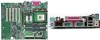
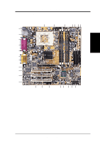
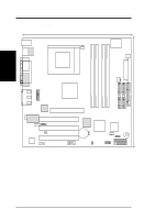
3. H/W SETUP Layout Contents 3. HARDWARE SETUP 3.2 Layout Contents Expansion 1) RIMMA1/A2/B1/B2 2) CPU 3) HEATSINK 3) PCI1/2/3 4) AGP 4X p.17 184-Pin System Memory Support p.19 Central Processing Unit (CPU) p.20 CPU Heatsink Retention Module Installation p.23 32-bit PCI Bus Expansion Slots p.25 Accelerated Graphics Port (AGP 4X) Slot Connectors 1) PS2KBMS 2) PS2KBMS p.26 PS/2 Mouse Connector (6 pin female) p.26 PS/2 Keyboard Connector (6 pin female) 3) PRINTER p.27 Parallel Port Connector (25 pin female) 4) COM1 5) USB 6) RJ45 7) IEEE 1394 8) GAME_AUDIO p.27 Serial Port Connector (One 9 pin male) p.28 Universal Serial Bus Ports (Two 4 pin female) p.28 Fast Ethernet Port Connector (optional) p.28 IEEE-1394 Controller Con.(optional)(6 pin male) p.29 Joystick/MIDI Connector (15 pin female) 9) GAME_AUDIO p.29 Audio Port Connectors (Three 1/8" Female) 10) FLOPPY p.29 Floppy Disk Drive Connector (34-1pin) 11) PRIMARY/SECONDARYIDE p.30 Primary/Secondary IDE Connectors (Two 40-1 pin) 12) USB2 p.30 USB Header (10-1 pin) 13) IA p.31 Internal Audio (4 pin SPDIF_OUT, CD_IN, AUX) 14) 1394_CON p.31 IEEE-1394 Controller Header (optional)(Two 8 pin) 15) CPU_FAN, PWR_FAN p.32 CPU, PWR, CHA Fan Connectors (Three 3 pin) CHA_FAN 16) SPDIFOUT p.33 Digital Audio Interface Connector (3 pin WOL) 17) WOLCON p.33 Wake-On-LAN Connector (3 pin) 18) IR p.34 Standard Infrared (SIR) Module Connector (5-pin IR) 19) AFPANEL p.34 iPanel Connector (24-1 pin) 20) ATXPWR, ATX12V p.35 ATX 12V Power Supply Connectors 21) IDELED p.35 IDE Activity LED (2-pin IDELED) 22) PWRLED (PANEL) p.36 System Power LED Lead (3 -1 pin) 23) KEYLOCK (PANEL) p.36 Keyboard Lock Switch Lead (2 pin) 24) SPEAKER (PANEL) p.36 System Warning Speaker Connector (4 pin) 25) MSG.LED (PANEL) p.36 System Message LED (2 pin) 26) SMI (PANEL) p.36 System Management Interrupt Switch Lead (2 pin) 27) PWRSW (PANEL) p.36 ATX Power / Soft-Off Switch Lead (2 pin) 28) RESET (PANEL) p.36 Reset Switch Lead (2 pin) ASUS P4T-M User's Manual 15
-
 1
1 -
2
-
3
-
4
-
5
-
6
-
7
-
8
-
9
-
 10
10 -
 11
11 -
 12
12 -
 13
13 -
 14
14 -
 15
15 -
 16
16 -
 17
17 -
 18
18 -
 19
19 -
 20
20 -
21
-
22
-
23
-
24
-
25
-
26
-
27
-
28
-
29
-
30
-
31
-
32
-
33
-
34
-
35
-
36
-
37
-
38
-
39
-
40
-
41
-
42
-
43
-
44
-
45
-
46
-
47
-
48
-
49
-
50
-
51
-
52
-
53
-
54
-
55
-
56
-
57
-
58
-
59
-
60
-
61
-
62
-
63
-
64
-
65
-
66
-
67
-
68
-
69
-
70
-
71
-
72
-
73
-
74
-
75
-
76
-
77
-
78
-
79
-
80
-
81
-
82
-
83
-
84
-
85
-
86
-
87
-
88
 |
 |
