Intel 850E User Manual - Page 35
ASUS P4T-M User's Manual, Power Supply Connectors 20-pin block ATXPWR 4-pin ATX12V, IDE Activity LED
 |
UPC - 735858158121
View all Intel 850E manuals
Add to My Manuals
Save this manual to your list of manuals |
Page 35 highlights
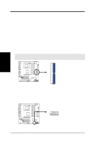
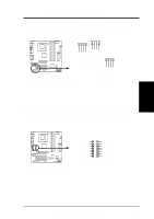
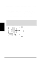
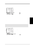
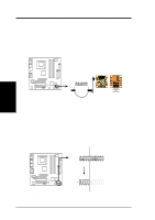
3. HARDWARE SETUP 20) Power Supply Connectors (20-pin block ATXPWR) (4-pin ATX12V) These connectors supply ATX 12V power. Each power supply plug inserts in one orientation only. Push down firmly and make sure the pins are aligned. IMPORTANT: For typical system configurations, an ATX12V power supply that can supply at least 230W and at least 8.5A on the +12V lead is required. For heavily-loaded configurations, an ATX12V power supply that can supply at least 300W is required. Your system may become unstable/unreliable and may experience difficulty in powering up if your power supply is inadequate. For WakeOn-LAN support, your ATX power supply (minimum recommended wattage: 230watts) must supply at least 720mA +5VSB. COM +12V DC Pin 1 P4T-M P4T-M ATX & Auxiliary Power Connectors ATXPWR COM +12V DC ATX12V Pin 1 +12.0VDC +5VSB PWR_OK COM +5.0VDC COM +5.0VDC COM +3.3VDC +3.3VDC +5.0VDC +5.0VDC -5.0VDC COM COM COM PS_ON# COM -12.0VDC +3.3VDC 21) IDE Activity LED (2-pin IDELED) This connector supplies power to the cabinet's IDE activity LED. Read and write activity by devices connected to the Primary/Secondary IDE and Primary/ Secondary ATA100 connectors will cause the LED to light up. 3. H/W SETUP Connectors P4T-M P4T-M IDE Activity LED TIP: If the case-mounted LED does not light, try reversing the 2-pin plug. IDELED ASUS P4T-M User's Manual 35
-
 1
1 -
2
-
3
-
4
-
5
-
6
-
7
-
8
-
9
-
10
-
11
-
12
-
13
-
14
-
15
-
16
-
17
-
18
-
19
-
20
-
21
-
22
-
23
-
24
-
25
-
26
-
27
-
28
-
29
-
 30
30 -
 31
31 -
 32
32 -
 33
33 -
 34
34 -
 35
35 -
 36
36 -
 37
37 -
 38
38 -
 39
39 -
 40
40 -
41
-
42
-
43
-
44
-
45
-
46
-
47
-
48
-
49
-
50
-
51
-
52
-
53
-
54
-
55
-
56
-
57
-
58
-
59
-
60
-
61
-
62
-
63
-
64
-
65
-
66
-
67
-
68
-
69
-
70
-
71
-
72
-
73
-
74
-
75
-
76
-
77
-
78
-
79
-
80
-
81
-
82
-
83
-
84
-
85
-
86
-
87
-
88
 |
 |
