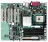
Intel BLKD865GBF Product Specification - Page 9

Desktop Board D865GBF/D865GLC Environmental Specifications

Page 9 highlights

Contents 13. LAN Connector LED States 47 14. LAN Connector LED States 48 15. Effects of Pressing the Power Switch 51 16. Power States and Targeted System Power 51 17. Wake-up Devices and Events 52 18. Fan Connector Function/Operation 54 19. System Memory Map 61 20. DMA Channels ...61 21. I/O Map ...62 22. PCI Configuration Space Map 63 23. PCI Configuration Space Bus Number Options 64 24. Interrupts ...65 25. PCI Interrupt Routing Map 67 26. Auxiliary Line In Connector 72 27. ATAPI CD-ROM Connector 72 28. Front Panel Audio Connector 72 29. Rear Chassis Fan Connector 73 30. ATX12V Power Connector 74 31. Processor Fan Connector 74 32. Main Power Connector 74 33. Front Chassis Fan Connector 75 34. Chassis Intrusion Connector 75 35. SCSI Hard Drive Activity LED Connector (Optional 78 36. Serial ATA Connectors 78 37. Auxiliary Front Panel Power/Sleep/Message-Waiting LED Connector 80 38. Front Panel Connector 80 39. States for a One-Color Power LED 81 40. States for a Two-Color Power LED 81 41. Front Panel Audio Connector/Jumper Block 84 42. BIOS Setup Configuration Jumper Settings 84 43. DC Loading Characteristics 88 44. Fan Connector Current Capability 88 45. Thermal Considerations for Components 91 46. MTBF Calculations ...92 47. Desktop Board D865GBF/D865GLC Environmental Specifications 92 48. Safety Regulations ...93 49. EMC Regulations...93 50. Product Certification Markings 95 51. Boot Device Menu Options 102 52. Supervisor and User Password Functions 104 53. BIOS Setup Program Menu Bar 105 54. BIOS Setup Program Function Keys 106 55. Maintenance Menu 106 56. Main Menu...107 57. Advanced Menu...108 58. PCI Configuration Submenu 109 59. Boot Configuration Submenu 111 60. Peripheral Configuration Submenu 112 ix

  • 1
  • 2
  • 3
  • 4
  • 5
  • 6
  • 7
  • 8
  • 9
  • 10
  • 11
  • 12
  • 13
  • 14
  • 15
  • 16
  • 17
  • 18
  • 19
  • 20
  • 21
  • 22
  • 23
  • 24
  • 25
  • 26
  • 27
  • 28
  • 29
  • 30
  • 31
  • 32
  • 33
  • 34
  • 35
  • 36
  • 37
  • 38
  • 39
  • 40
  • 41
  • 42
  • 43
  • 44
  • 45
  • 46
  • 47
  • 48
  • 49
  • 50
  • 51
  • 52
  • 53
  • 54
  • 55
  • 56
  • 57
  • 58
  • 59
  • 60
  • 61
  • 62
  • 63
  • 64
  • 65
  • 66
  • 67
  • 68
  • 69
  • 70
  • 71
  • 72
  • 73
  • 74
  • 75
  • 76
  • 77
  • 78
  • 79
  • 80
  • 81
  • 82
  • 83
  • 84
  • 85
  • 86
  • 87
  • 88
  • 89
  • 90
  • 91
  • 92
  • 93
  • 94
  • 95
  • 96
  • 97
  • 98
  • 99
  • 100
  • 101
  • 102
  • 103
  • 104
  • 105
  • 106
  • 107
  • 108
  • 109
  • 110
  • 111
  • 112
  • 113
  • 114
  • 115
  • 116
  • 117
  • 118
  • 119
  • 120
  • 121
  • 122
  • 123
  • 124
  • 125
  • 126
  • 127
  • 128
  • 129
  • 130
  • 131
  • 132
  • 133
  • 134
  • 135
  • 136
  • 137
  • 138
  • 139
  • 140
  • 141
  • 142

Contents
ix
13.
LAN Connector LED States
........................................................................................
47
14.
LAN Connector LED States
........................................................................................
48
15.
Effects of Pressing the Power Switch
.........................................................................
51
16.
Power States and Targeted System Power
................................................................
51
17.
Wake-up Devices and Events
.....................................................................................
52
18.
Fan Connector Function/Operation
.............................................................................
54
19.
System Memory Map
..................................................................................................
61
20.
DMA Channels
...........................................................................................................
61
21.
I/O Map
......................................................................................................................
62
22.
PCI Configuration Space Map
....................................................................................
63
23.
PCI Configuration Space Bus Number Options
..........................................................
64
24.
Interrupts
....................................................................................................................
65
25.
PCI Interrupt Routing Map
..........................................................................................
67
26.
Auxiliary Line In Connector
.........................................................................................
72
27.
ATAPI CD-ROM Connector
........................................................................................
72
28.
Front Panel Audio Connector
.....................................................................................
72
29.
Rear Chassis Fan Connector
.....................................................................................
73
30.
ATX12V Power Connector
..........................................................................................
74
31.
Processor Fan Connector
...........................................................................................
74
32.
Main Power Connector
...............................................................................................
74
33.
Front Chassis Fan Connector
.....................................................................................
75
34.
Chassis Intrusion Connector
.......................................................................................
75
35.
SCSI Hard Drive Activity LED Connector (Optional)
...................................................
78
36.
Serial ATA Connectors
...............................................................................................
78
37.
Auxiliary Front Panel Power/Sleep/Message-Waiting LED Connector
........................
80
38.
Front Panel Connector
...............................................................................................
80
39.
States for a One-Color Power LED
.............................................................................
81
40.
States for a Two-Color Power LED
.............................................................................
81
41.
Front Panel Audio Connector/Jumper Block
...............................................................
84
42.
BIOS Setup Configuration Jumper Settings
................................................................
84
43.
DC Loading Characteristics
........................................................................................
88
44.
Fan Connector Current Capability
..............................................................................
88
45.
Thermal Considerations for Components
...................................................................
91
46.
MTBF Calculations
.....................................................................................................
92
47.
Desktop Board D865GBF/D865GLC Environmental Specifications
............................
92
48.
Safety Regulations
.....................................................................................................
93
49.
EMC Regulations
........................................................................................................
93
50.
Product Certification Markings
....................................................................................
95
51.
Boot Device Menu Options
.......................................................................................
102
52.
Supervisor and User Password Functions
................................................................
104
53.
BIOS Setup Program Menu Bar
...............................................................................
105
54.
BIOS Setup Program Function Keys
........................................................................
106
55.
Maintenance Menu
...................................................................................................
106
56.
Main Menu
................................................................................................................
107
57.
Advanced Menu
........................................................................................................
108
58.
PCI Configuration Submenu
.....................................................................................
109
59.
Boot Configuration Submenu
....................................................................................
111
60.
Peripheral Configuration Submenu
...........................................................................
112