Intel BLKD945GNTLKR Product Specification - Page 57
Back Panel Connectors For 6-Channel 5.1 Audio Subsystem
 |
View all Intel BLKD945GNTLKR manuals
Add to My Manuals
Save this manual to your list of manuals |
Page 57 highlights
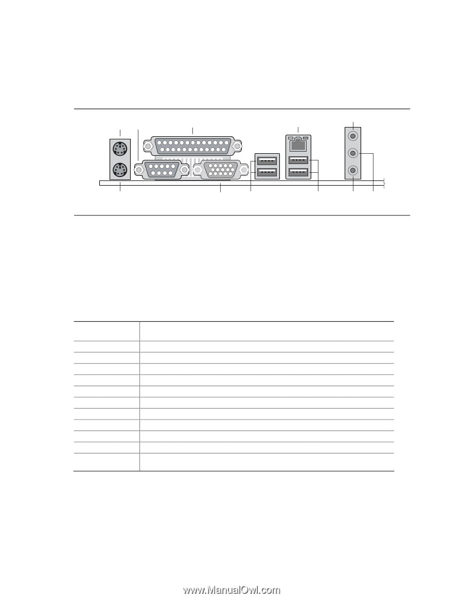
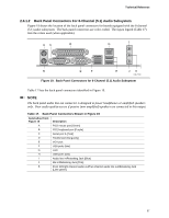
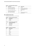
Technical Reference 2.8.1.2 Back Panel Connectors For 6-Channel (5.1) Audio Subsystem Figure 19 shows the location of the back panel connectors for boards equipped with the 6-channel (5.1) audio subsystem. The back panel connectors are color-coded. The figure legend (Table 17) lists the colors used (when applicable). AC D I G B E F H JK OM17559 Figure 19. Back Panel Connectors for 6-Channel (5.1) Audio Subsystem Table 17 lists the back panel connectors identified in Figure 19. NOTE The back panel audio line out connector is designed to power headphones or amplified speakers only. Poor audio quality occurs if passive (non-amplified) speakers are connected to this output. Table 17. Back Panel Connectors Shown in Figure 19 Item/callout from Figure 19 Description A PS/2 mouse port [Green] B PS/2 keyboard port [Purple] C Serial port A [Teal] D Parallel port [Burgundy] E VGA port F USB ports (two) G LAN H USB ports (two) I Audio line in/Retasking Jack [Blue] J Mic in/Retasking Jack [Pink] K Front left/right channel audio out/Two channel audio line out/Retasking Jack [Lime green] 57
-
 1
1 -
2
-
3
-
4
-
5
-
6
-
7
-
8
-
9
-
10
-
11
-
12
-
13
-
14
-
15
-
16
-
17
-
18
-
19
-
20
-
21
-
22
-
23
-
24
-
25
-
26
-
27
-
28
-
29
-
30
-
31
-
32
-
33
-
34
-
35
-
36
-
37
-
38
-
39
-
40
-
41
-
42
-
43
-
44
-
45
-
46
-
47
-
48
-
49
-
50
-
51
-
 52
52 -
 53
53 -
 54
54 -
 55
55 -
 56
56 -
 57
57 -
 58
58 -
 59
59 -
 60
60 -
 61
61 -
 62
62 -
63
-
64
-
65
-
66
-
67
-
68
-
69
-
70
-
71
-
72
-
73
-
74
-
75
-
76
-
77
-
78
-
79
-
80
-
81
-
82
-
83
-
84
-
85
-
86
-
87
-
88
-
89
-
90
-
91
-
92
-
93
-
94
 |
 |